background image

Eye


III+


I

nstallation Guide


Page  63


Advanced Configuration - Modifying Settings


3.


Through Modem 


Step 1:

 Make sure your PC is connected to a modem and is turned on. 


Step 2

: From Start menu, select 

Program Files   

Eye III+   Transmitter Configuration

 to run 

the Configuration


program. Then, the Configuration program should appear. 
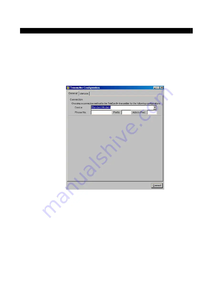
 

Step 3:

 Click on the 

General

 page. In the

 Connection 

group with

 Device

 menu,


choose the suitable 

modem driver and enter the phone number and prefix number, if necessary. Enter the 

administrator password at the 

Admin Pwd

 field (The default one is 

“000000”

). 


Step 4:

 Click the 

Connect

 button. Please wait while it is connecting the transmission unit. 


Step 5:

 A 

Completed(

[baud rate]

)

 message box will be displayed. The transmitter default information 

will be displayed at each fields. 


Step 6:

 Now you can make the necessary changes on fields provided. 


Step 7:

 After changing the settings, press 

Save and Exit

 button to write the information back to the 

transmitter.


Step 8:

 Please wait until it shows 

Completed(

[baud rate]

)

 message box, where 

[baud rate]


shows 

the modem baud rate you are connecting to. 


Note: Every time when you want to write the settings to the transmitter, you have to do the 

Connect

 action before 

you write. Moreover, the 

Connect

 button can only be pressed once when you start the configuration program. You 

may need to restart the program and 

Connect

 again if you want to re-write the changing field. 

Содержание VT3-16BA

Страница 1: ...Transmission Unit Installation Guide...

Страница 2: ...trademarks are the property of their respective owners Copyright c 2003 Signal Communications Limited A member of Eye Group All rights reserved Version 4 5 Limits of Liability and Disclaimer of Warra...

Страница 3: ...ns may cause harmful interference to radio communications However there is no guarantee that interference will not occur in a particular installation If this equipment does cause harmful interference...

Страница 4: ...stration Checking 11 Video Mode 11 Built in Web Server 11 Site Monitoring Method 12 SECTION 4 sureLINK TECHNOLOGY 13 sureLINK Address 13 How to apply 14 Transmitter Modification 16 SECTION 5 SYSTEM CO...

Страница 5: ...er Configuration 40 Transmitter Installation 41 D1 For Direct modem dial up access Transmitter Installation 43 Transmitter Configuration Procedure 44 D2 For PPP dial up service access Transmitter Inst...

Страница 6: ...Model VT3 1CA VT3 2CA VT3 4BA VT3 4CA 64 Model VT3 4B VT3 4C 65 Model VT3 8BA VT3 8CA 66 Model VT3 16BA VT3 16CA 67...

Страница 7: ......

Страница 8: ...technology allows low cost dynamic IP broadband Internet connection Say goodbye to the expensive static IP environment Powered by its unique Dual Connectivity Eye III also supports simultaneous netwo...

Страница 9: ...deo transmission up to 30 fps over LAN for NTSC up to 25 fps over LAN for PAL up to 20 fps on PSTN 1 2 4 8 16 video inputs with 1 4 8 16 alarm inputs respectively Digital video recording Web based vid...

Страница 10: ...Standard BNC connectors for color video sources A composite video signal should be supplied to these connectors Power OUTPUT ALARM RELAY Port OUTPUT This port is used for external device power supply...

Страница 11: ...nd ready to function AUX Port Reserved for remote Pan Tilt Zoom operation Used for configuring the Eye III transmitter s internal settings Contains Transparent Aux Port function so that data from exte...

Страница 12: ...er with Alarm VIDEO INPUT Connectors CH1 CH2 CH4 Standard BNC connectors for color video sources A composite video signal should be supplied to these connectors ALARM SWITCH Port This port is used for...

Страница 13: ...Eye III transmitter is connecting to the network and ready to function AUX Port Reserved for remote Pan Tilt Zoom operation Used for configuring the Eye III transmitter s internal settings Contains T...

Страница 14: ...LED Status COL LED when on indicates that collision is occurring on the network LINK LED when on indicates that Eye III transmitter is connecting to the network and ready to function AUX Port Reserved...

Страница 15: ...ge 8 Interface Description Ethernet 10 100 Base T COL LINK ALARM SW Ethernet 10 100 Base T COL LINK ALARM SW The panels of the Eye III transmitter model are shown below The panels of the Eye III trans...

Страница 16: ...cting Eye III transmitter to the corporate computer network e g LAN Collision Link LED Status COL LED when on indicates that collision is occurring on the network LINK LED when on indicates that Eye I...

Страница 17: ...Pin 37 DRY CONTACT 2 B Pin 19 RESERVED For model Pin 1 ALARM IN 1 Pin 20 GND Pin 2 ALARM IN 2 Pin 21 GND Pin 3 ALARM IN 3 Pin 22 GND Pin 4 ALARM IN 4 Pin 23 GND Pin 5 ALARM IN 5 Pin 24 GND Pin 6 ALARM...

Страница 18: ...eration This setting should be configured during the installation of the transmitter For ideal performance in speed please choose the Speed option Note that you cannot set the video performance at the...

Страница 19: ...Software You have to choose one of the System Configuration Methods in later section to configure Eye III s transmitter before use so as to make it function properly The transmitter configuration prog...

Страница 20: ...ive and convenient remote live video monitoring anytime and anywhere sureLINK Address A sureLINK address domain name such as www hkoffice teleeye teleeye net will be assigned for each transmitter so t...

Страница 21: ...ply for sureLINK Address You can apply for sureLINK by visiting our web site at http www TeleEye com Step1 Sign up to create your user account Step 2 Login the page using the your registered name and...

Страница 22: ...Normally it requires about 2 to 3 working days to activate sureLINK for your transmitter You will receive an e mail to notify you that sureLINK is activated Transmitter Modification Since the sureLINK...

Страница 23: ...Step 2 Enter the Old Registration Code New Transmitter Serial Number and New Registration Code at each field provided Click Modify button to submit the form If the above procedure is completed succes...

Страница 24: ...ction What You Need Hardware PC Minimum Requirement Pentium II 350 MHz Windows 95 98 ME NT or 2000 Operating System 64MB RAM for Windows 95 98 ME 128MB RAM for Windows NT 2000 Eye III Transmission Uni...

Страница 25: ...ent serial cable The cable needs a DB 9 female connector for PC at one end and a DB 9 male connector for Eye III transmitter at the other Software Transmitter Configuration software A PC with Transmit...

Страница 26: ...ed straight through 9 to 9 serial cable from the serial port of the computer to the AUX port of the Eye III transmitter Step 2 Turn on the Eye III transmitter A blue light at the front panel will flas...

Страница 27: ...e box will be displayed The transmitter default information will be displayed at each field Step 8 Configure the Registration Checking and Video Mode group settings Leave the Transmitter s IP group wi...

Страница 28: ...an one camera is installed plug the BNC cables to the Eye III transmitter CH2 to CH4 8 16 sequentially For 2 4 8 16 Cam model only Step 6 Connect alarm sensor to the corresponding pins of the ALARM SW...

Страница 29: ...8 16 video sources in all PAL or NTSC format PC Minimum Requirement Pentium II 350 MHz Windows 95 98 ME NT or 2000 Operating System 64MB RAM for Windows 95 98 ME 128MB RAM for Windows NT 2000 Power A...

Страница 30: ...RS3 AD software Information Valid IP address for the transmitter Administrator Password for the transmitter The default administrator password is 000000 You can change it in the reception software Por...

Страница 31: ...onfiguration program should appear as shown below Step 5 Click on the General page In the Connection group with Device menu choose the suitable serial port COM1 or COM 2 or so on for current connectio...

Страница 32: ...n Enable the Built in Web Server so that you can see video through web browser Step 11 Ensure all settings are correct then press the Save and Exit button Step 12 Please wait until it shows Completed...

Страница 33: ...n one camera are installed plug the BNC cables to the Eye III transmitter CH2 to CH4 8 16 sequentially For 2 4 8 16 Cam model only Step 4 Connect alarm sensor to the corresponding pins of the ALARM SW...

Страница 34: ...7 System Configuration and Installation B2 For Broadband Internet Connection with Static IP Please follow the step of B1 Internal LAN Access except you have to set the Gateway IP of your LAN when conf...

Страница 35: ...8 ME NT or 2000 Operating System 64MB RAM for Windows 95 98 ME 128MB RAM for Windows NT 2000 Power Adapter It is a 9 to 12 VDC power adapter Serial Cable It is a shielded straight through DTE Data Ter...

Страница 36: ...sword is 000000 You can change it in the reception software Port number for the transmitter default value is 1024 Your network gateway address If you don t familiar with this you can use one suggested...

Страница 37: ...Transmitter Configuration to run the Configuration program Then the Configuration program should appear as shown below Step 5 Click on the General page In the Connection group with Device menu choose...

Страница 38: ...mple if your router s IP is 192 168 0 1 then the transmitter s IP can become 192 168 0 2 with subnet mask 255 255 255 0 Step 9 Configure the Registration Checking and Video Mode settings Step 10 You c...

Страница 39: ...ake sure that your cable connection between the transmitter and your PC is well connected And you can close the configuration program and redo step 4 Step 15 you have to ensure that the router in use...

Страница 40: ...That means if the router IP is 192 168 0 1 and subnet mask is 255 255 255 0 your PC s IP address must be 192 168 0 X where X is between 2 and 254 Example of Router Setting External port 1024 Internal...

Страница 41: ...UT of the CCD camera then plug the other end to the Eye III transmitter s VIDEO INPUT connector CH1 preferred If more than one camera is installed plug the BNC cables to the Eye III transmitter CH2 to...

Страница 42: ...items are required Hardware Eye III Transmission Unit The video transmitter supports up to 2 4 8 16 video sources in all PAL or NTSC format PC Minimum Requirement Pentium II 350 MHz Windows 95 98 ME...

Страница 43: ...ss for the transmitter Administrator Password for the transmitter The default administrator password is 000000 You can change it in the reception software Port number for the transmitter default value...

Страница 44: ...he General page In the Connection group with Device menu choose the suitable serial port COM 1 or COM 2 or so on for current connection to the transmitter At the same time enter the administrator pass...

Страница 45: ...tep 10 At the Gateway page leave the Gateway IP field as the default value 0 0 0 0 Step 11 At the sureLINK page Enable the sureLINK feature and enter the sub domain name should be registered before us...

Страница 46: ...d your PC is well connected And you can close the configuration program and redo step 4 Note For advanced user you can assign other IP addresses for PC and transmitter rather than that provided above...

Страница 47: ...will then become a bridge for the connection between the transmitter and the Internet Step 14 Install TeleEye Proxy Server into your PC Step 15 Double click the icon the following window will then be...

Страница 48: ...ghout the connection You will see a Eye Proxy icon on your system tray Transmitter Installation After you configured the transmitter you can place the transmitter to your remote side Switch ADSL Modem...

Страница 49: ...ye III transmitter s VIDEO INPUT connector CH1 preferred If more than one camera plug the BNC cable to the Eye III transmitter CH2 to CH2 4 8 16 sequentially For 2 4 8 16 Cam model only Step 5 Connect...

Страница 50: ...e hub power connector At the same time plug the hub power supply into a wall let and power on the hub Step 4 Plug one end of the BNC cable into the VIDEO OUTPUT of the CCD camera then plug the other e...

Страница 51: ...hould light up Step 9 You may now use the TeleEye III Reception Software to connect to the transmitter For the instructions of using the software please refer to the TeleEye III Reception Software Use...

Страница 52: ...ick the OK button Step 7 Disable the PPP mode function Double click the icon of the Transmitter Configuration Software T3Config and connect it to the VT transmitter Click and select the PPP Mode Tab t...

Страница 53: ...dy to dial up the modem to access the Transmitter Double click and open the TeleEye III Reception Software WRS3 AD Reception Software and click connect icon to access the direct modem dial up service...

Страница 54: ...A 1X Wireless modem Effective valid account of CDMA 1X wireless Internet service access account Registered sureLINK address For the details of sureLINK please refer to Section 9 sureLINK Technology Ey...

Страница 55: ...ection 2 Alarm Definition Step 7 Plug the A C adapter to A C power source to power on the CDMA 1X wireless modem Step 8 Plug the round end of the A C adaptor into the socket marked on the Eye III tran...

Страница 56: ...e the modem baud rate please refer to modem user manual Step 6 Then click the OK button Step 7 Enable the PPP Mode Function Double click the icon of the Transmitter Configuration Software T3Config and...

Страница 57: ...umber If required 5 Enter your ISP dialing account phone number 6 Enter the Extra AT Command It is used for advanced users who need extra settings for the dialup modem The settings allowed is specific...

Страница 58: ...roup Please ask your ISP to get this information 5 Ensure all settings are correct then press the Save and Exit button Step 11 Please wait until it shows Write Process Completed Message box If Transmi...

Страница 59: ...P connection information of the following steps 1 Enter your sureLINK address 2 Select the TCP IP into connect using 3 Enter your password 4 Ensure all settings are correct then press the Connect butt...

Страница 60: ...nd Java Support Before using the web service you have to make sure that you have ENABLED the Built in Web Server feature when configuring the transmitter For details please read Transmitter Configurat...

Страница 61: ...login password and press Login button A new page will be displayed You can choose the cameras by clicking the hyperlink on the left Note If you have any problem on opening the page please go to http j...

Страница 62: ...the Internet If you discover that you cannot be able to access on the Internet after applying the settings you have to undo the settings or re install the software provided by your ISP and retry the...

Страница 63: ...Protocol over Ethernet Note that the name of these two TCP IP adapters may be different on your computer You have to identify the purpose of each corresponding adapter Step 3 Choose TCP IP Your Ethern...

Страница 64: ...Appendix Step 7 Select your Ethernet card name on the field you will see a IP address on the field Ensure that that is the same as you have set before i e 192 168 0 3 If it is not so please repeat ste...

Страница 65: ...ou discover that you cannot be able to access to the Internet after applying the settings you have to undo the settings or re install the software provided by your ISP and retry the steps again Step 1...

Страница 66: ...cmd at Open field and pressed OK button then type ipconfig on the DOS prompt you will see a IP set on your computer Router Configuration Port Mapping in your Router For PLANET Internet SOHO Router XRT...

Страница 67: ...transmitter settings By referring to which method you are currently connecting to the transmitter to view the video you can choose ONE of the methods below to make the changes Note that the transmitt...

Страница 68: ...ting the transmission unit If Transmission unit not found message is displayed make sure that your cable connection between the transmitter and your PC is well connected And you can close the configur...

Страница 69: ...ter the administrator password at the Admin Pwd field The default one is 000000 Step 5 Click the Connect button Please wait until it shows Read Process Completed Message box If Transmission unit not f...

Страница 70: ...e wait while it is connecting the transmission unit Step 5 A Completed baud rate message box will be displayed The transmitter default information will be displayed at each fields Step 6 Now you can m...

Страница 71: ...IVE IMAGE COMPRESSION ALARM INPUT 1 CHANNEL NC NO 4 INDEPENDENT CHANNELS NC NO OUTPUT 1 CHANNEL DRY CONTACT CONTACT RATING 24 Vdc 1A SERIAL PORT TYPE RS 232C DB 9 MALE CONNECTOR RATE 2400 115200 bps F...

Страница 72: ...BNC WITH 75 TERMINATION FRAME CAPTURE RESOLUTION H x V 128 x 96 256 x 192 512 x 384 160 x 120 320 x 240 640 x 480 PIXELS GRAY LEVELS 256 COLORS 16 MILLION COMPRESSION SCALEABLE ADAPTIVE IMAGE COMPRESS...

Страница 73: ...8 CHANNELS 1 0Vpp COMPOSITE BNC WITH 75 TERMINATION FRAME CAPTURE RESOLUTION H x V 128 x 96 256 x 192 512 x 384 160 x 120 320 x 240 640 x 480 PIXELS GRAY LEVELS 256 COLORS 16 MILLION COMPRESSION SCALE...

Страница 74: ...T3 16CA VT3 16BA VIDEO STANDARD P PAL CCIR 625 LINES 50 FIELDS PER SECOND N NTSC EIA 525 LINES 60 FIELDS PER SECOND INTERFACE 16 CHANNELS 1 0Vpp COMPOSITE BNC WITH 75 TERMINATION FRAME CAPTURE RESOLUT...

Страница 75: ...STOP BIT N 8 1 FLOW CONTROL HARDWARE RTS CTS PROTOCOL EFFICIENT ERROR CONTROL PROTOCOL MODEM CONTROL HAYES COMMANDS POWER REQUIREMENT INPUT VOLTAGE 9 12V DC POWER CONSUMPTION 12W MAX ENVIRONMENT COND...

Отзывы: