background image


SeaBat UI - User Manual 

Service  

  63 


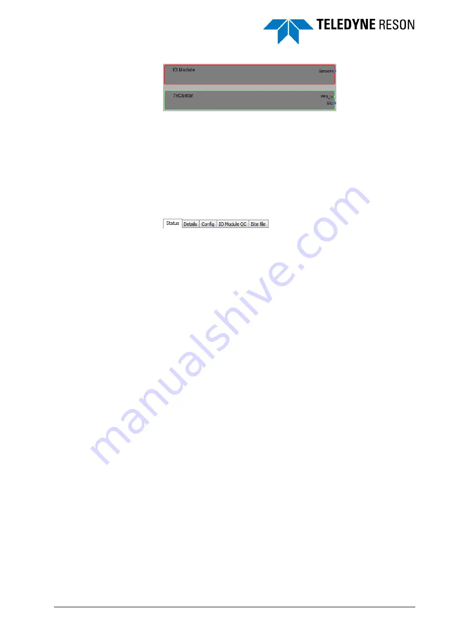
Figure 5-2 

Module in error (red), 7KCenter correct (green) 

 The error message will be displayed in the tab Status (see below). When 
the error is a timeout the component will be red, but no information will be 
displayed in the Status. 

5.3 Information 

The available information of the sonar system is displayed on the right 
side in the Service. The different types of information will be ordered 
under several tabs: 


Figure 5-3 

Service tabs 


Status

 (see below) 

In the Status page the errors with the relevant information are 
displayed. 

With ‘Ctrl+B’ extra BITE 
information of the selected 
item becomes available in 
the Details and Config 
page. 


Details

 (see page 64) 

In the Details page the BITE information of the selected 
component, wire or pin in the diagram is displayed. 


Config


In the Config page the preconfigured settings and the serial/version 
numbers for the software and firmware of the installed sonar 
system is displayed. 


IO Module QC

 (see page 66) 

In the IO Module QC page the different devices that are interfaced 
through the IO Module pane will be displayed. 


BITE File


In the BITE File page the contents of the BITE file is displayed. This 
page 

is only available after the keystroke ‘Ctrl+B’. 

5.3.1 Status 

In the Status page the errors or warning of the system are displayed. 
When no error or warning occurs this page will be empty. 

When errors occur then for each part of the sonar system that is in error a 
message will be displayed in the Status page. Below an example of some 
messages is displayed. 

Содержание SeaBat UI

Страница 1: ...User Manual SeaBat UI Version 1 1 0 December 2013 Teledyne RESON B V Stuttgartstraat 42 44 3047 AS Rotterdam The Netherlands Tel 31 0 10 245 15 00 www teledyne reson com ...

Страница 2: ... SeaBat UI version 4 0 0 10 1 0 5 12 10 2012 Updated to SeaBat UI version 4 0 0 8 1 0 4 05 07 2012 Updated to SeaBat UI version 4 0 0 4 1 0 3 04 06 2012 Minor updates 1 0 2 24 05 2012 Updated to the latest SeaBat UI version 1 0 1 14 05 2012 New items added to the SeaBat UI User Manual 1 0 0 26 04 2012 First version of the SeaBat UI User Manual ...

Страница 3: ...n Settings Dialog 10 3 3 2 About Dialog 12 3 3 3 Licensed Features Dialog 12 3 3 4 Help File 13 3 3 5 Color Mode 13 3 3 6 Service Mode 13 3 3 7 Operation Mode 13 3 3 8 Save Snapshot 13 3 3 9 Start Record AVI 13 3 3 10 Start Record RDR 14 3 3 11 Start the Tracker 14 3 3 12 Pitch Stabilization 14 3 3 13 Roll Stabilization 14 3 3 14 1PPS 15 3 3 15 Normalization 15 3 3 16 BITE 15 3 4 Screen Toolbar an...

Страница 4: ... 32 4 6 1 Depth Gate 32 4 6 2 Range Gate 34 4 6 3 Adaptive Gate 34 4 6 4 Tracker 34 4 6 5 Coverage angle 35 4 6 6 Multi detect 35 4 7 Display 36 4 8 Recording 38 4 8 1 Raw data Record Selection 39 4 8 2 Status 40 4 9 Hardware 40 4 9 1 Motion Stabilization 41 4 9 1 1 Roll Stabilization 41 4 9 1 2 Pitch Stabilization 42 4 9 2 PPS Configuration 42 4 9 3 Trigger Configuration 43 4 9 4 Ping Settings 43...

Страница 5: ... 51 4 11 3 Zoom Functions 52 4 11 4 Wedge 53 4 11 5 Water Column 55 4 11 6 Detect 55 4 11 7 Sidescan 56 4 11 8 Snippets 57 4 11 9 Helmsman 58 5 Service 61 5 1 Introduction 61 5 2 Diagram 62 5 3 Information 63 5 3 1 Status 63 5 3 2 Details 64 5 3 3 IO Module QC 66 ...

Страница 6: ...ge Water Column and snippets screen switched on button highlited but Sidescan screen off button greyed 21 Figure 4 9 Double arrow and cross to resize screens 21 Figure 4 10 Advanced Controls 22 Figure 4 11 Custom checkbox ticked to set the number of beams 22 Figure 4 12 Custom checkbox ticked to set the number of beams 22 Figure 4 13 Custom checkbox ticked to set the number of beams 23 Figure 4 14...

Страница 7: ...idth 42 Figure 4 54 Swath under roll stabilization 42 Figure 4 55 Hardware part for the PPS Configuration 42 Figure 4 56 Hardware part for the Trigger Configuration 43 Figure 4 57 Example of trigger output with Delay 0 and Pulse length 1 43 Figure 4 58 Hardware part for the Ping Settings 43 Figure 4 59 Hardware part for the Dual Head 44 Figure 4 60 Hardware part for the Dual head with the Slave co...

Страница 8: ...n this example when the distance exceeds 4 meters 59 Figure 5 1 Diagram in the Service of a SeaBat SV2 62 Figure 5 2 Module in error red 7KCenter correct green 63 Figure 5 3 Service tabs 63 Figure 5 4 Example of error messages in the Status page 64 Figure 5 5 Example of available information here Charger in the Details page 65 Figure 5 6 Example of timed outs in the Charger 65 Figure 5 7 IO Module...

Страница 9: ...e toolbar see page 5 In the chapter Operation the operation mode of the SeaBat UI is discussed The different panes that can be used in conjunction with the screens will be explained in detail see page 17 In the last chapter Service the status of the complete sonar system the temperature voltage communication status and other parameters is discussed with explaining the system diagram and how the op...

Страница 10: ......

Страница 11: ...Operation mode with the four screens displayed and a normalization process will run indicated by a progress bar d The external clock with 1PPS and the sound velocity probe have to be interfaced with the 7K system This can be done in the IO Module see page 28 e For a roll and or pitch stabilization the motion sensor has to be connected to the right port on the sonar system Enable in the hardware th...

Страница 12: ... select the Depth Range or Adaptive gate in the Main pane See page 20 k Set the Tracker on to get a fully automated mode of the operation see page 14 l Before the recording of the sonar data can be started the record selection and the path for the recorded files have to set in the Recording pane see page 38 m Use the Display pane to set the right settings for the screens see page 36 ...

Страница 13: ...een toolbar is working 3 2 Arranging the Panes The SeaBat UI uses tabs on the right side and at the bottom to open the settings panes the control pane and the messages pane of the SeaBat UI 3 2 1 Panes The settings panes on the right side are Display Detection Recording Hardware IO Module Pipe And the three panes at the bottom are Main Advanced Messages In this chapter will be explained how the pa...

Страница 14: ... Manual 3 2 1 1 Opening and hiding Panes Move the pointer above a tab on the right side or bottom of the view and left click to open the Pane Move the pointer outside the Pane and left click to hide the Pane again Figure 3 1 Display pane ...

Страница 15: ...de The pin will change to the pane is docked pinned and will stay open even when the pointer is moved outside the pane and left clicked The pane is now in Docking mode Click on to undock the pane When the pane is closed after the pane is docked and undocked the tab will be placed as last tab on the right side and as right tab on the bottom So the order of the tabs will be changed by open and dock ...

Страница 16: ... the window is dragged It is possible to move the floating window outside the frame of the SeaBat UI Figure 3 3 Floating window with the guide diamonds for the settings panes The guide diamonds helps to re dock the settings panes to the left or right side as displayed above and the Main Advanced and Messages to the top or bottom of the view Dragged the floating window to one of the guide diamonds ...

Страница 17: ...and the two windows will become one window with two tabs at the bottom of the window This last option is only valid for the settings panes Figure 3 4 Two windows combined with two tabs Double click on the title bar of the combined window to make both windows docked panes again It is also possible to check Docking in the context menu see below of the combined window Both the panes will be docked to...

Страница 18: ...ome in the Docking mode The second picture is the context menu when the pane is in the Docking mode Check Auto Hide or Floating to go to another mode The third picture is the context menu when the window is in the Floating mode Check Docking to change the mode to the Docking mode It is not possible to go from Floating direct to Auto Hide mode 3 3 SeaBat UI Toolbar Figure 3 6 Toolbar of the SeaBat ...

Страница 19: ... size can be set to Small Medium and Big and is only for the font in the panes Units The unit for the depth and range in the Seabat UI can be set At the moment only the unit Meters is available Sonar Check the checkbox to reset the sonar Sonar Check the checkbox to restore the factory settings of the sonar Sonar System Shutdown The software and firmware will be halted followed by a power shutdown ...

Страница 20: ...g Click on to open the about dialog Figure 3 8 About SeaBat UI dialog 3 3 3 Licensed Features Dialog Click on to open the dialog Figure 3 9 Licensed Features dialog The Licensed Features dialog displays the licenses of the feature packages as purchased by the user ...

Страница 21: ... 3 3 6 Service Mode Click on Service to open the view with the BITE system information See for more information the chapter Service on page 61 3 3 7 Operation Mode Click on Operation to open the view with the sonar data See for more information the chapter Operation on page 17 3 3 8 Save Snapshot Click on Snapshot to create an image of the application window The snapshot will be stored as a JPG wi...

Страница 22: ... automated mode of operation All parameters including range gain power and swath width are set by the system on the basis of the quality of the collected data Once the Tracker has been selected no further operator input is required Click on the highlighted text Tracker to stop the Tracker and the green led indicator becomes the button again 3 3 12 Pitch Stabilization The pitch stabilization is onl...

Страница 23: ...re Blue When the SeaBat UI is started the Normalization is not yet initialized Grey The Normalization is not done Green The Normalization is done Yellow Orange The Normalization is busy at this moment the normalization takes place Red Error level The Normalization has failed In the Hardware Settings the status of the Normalization can be monitored see page 46 3 3 16 BITE The led indicator will ind...

Страница 24: ...s pops up automatically Functions of the screen toolbar are also available in a context menu Right click in the screen and the context menu wills popup This toolbar and context menu could be used to adjust the properties of the screen See chapter Operation on page 17 for more details ...

Страница 25: ...hen the SeaBat UI was closed before Figure 4 1 Seabat UI with four screens In this chapter the different panes and the four screens will be discussed With the main and advanced pane accessible by the tabs at the bottom of the SeaBat UI the sonar can be controlled and with the settings in the settings panes accessible by the tabs at the right side of the SeaBat UI the sonar data can be presented ...

Страница 26: ...l properties of the screens of the Operation Recording see page 38 In the Recording pane the operator can selected which data is recorded and the recording information is displayed Hardware see page 40 In the Hardware pane the operator can setup the roll and or pitch stabilization and can setup for a dual head system Pipe see page 46 In the pipe pane the operator can setup the settings for the pip...

Страница 27: ...increase or decrease the amount of power acoustic energy that is transmitted into the water Figure 4 4 Power If the power is set to OFF the system will not ping but it will continue to receive data provided that the ping rate is not set to 0 The sonar system will act as a passive sonar by only receiving data This is a feature that is very useful for monitoring the ambient noise and interference fr...

Страница 28: ...h setting allows the operator to change the pulse length of the transmitted signal Figure 4 6 Pulse Length For a given power setting a narrower pulse length will provide a higher resolution at a shorter range A wider pulse length will provide better range but a lower resolution image In certain conditions for example in turbid waters the narrower pulse length may not operate well In such circumsta...

Страница 29: ...screen switching on the Detect screen or switching off both The Sidescan Helsman button has three functions switching on the Sidescan screen switching on the Helsman screen or switching both off The size of the screens can be modified by dragging the horizontal or vertical divider up down or left right To drag the divider move the cursor over the divider and the cursor becomes a double arrow indic...

Страница 30: ... such as wrecks and vertical structures such as harbor walls Equi Angle should be used in preference to Best Coverage see also Best Coverage When the Custom checkbox is ticked the number of beams can be set by the operator This allows the operator to be able to capture the highest detail using the highest beam density needed In very shallow water less beams can be used to reduce data volumes Figur...

Страница 31: ... due to the large overlap between beams towards the edge of the sector When the custom checkbox is ticked the number of beams can be set by the operator Figure 4 13 Custom checkbox ticked to set the number of beams When additional to the custom checkbox the Constant spacing checkbox is ticked the spacing distance between de beams can be set Flexmode Gives a combination of a high density of beams o...

Страница 32: ...density spacing is set by the slides in the wedge This slides become visible in the wedge when the Flexmode is selected Drag the slides and the high density spacing changes Figure 4 16 Slides in the wedge to change the high density spacing 4 3 2 Horizontal Steering Figure 4 17 Steering ...

Страница 33: ...d The limitation is that the outer beam cannot be steered past 5 from the horizontal When the swath is steered this way the individual beam widths increase with the steering angle A beam steered at 60 is twice the width of a beam steered at 0 Figure 4 18 With a swath of 120 the maximum steering is 25 85 120 2 Figure 4 19 With a swath of 60 the maximum steering is 55 85 60 2 4 3 3 Coverage Angle Th...

Страница 34: ...is operating in a high reverb environment where echoes of the previous ping are contaminating the current ping 4 3 5 Frequency For a dual frequency system the frequency setting allows the operator to switch the frequency on the fly without restarting the 7K Center All sonar controls will then be dedicated to the selected frequency Figure 4 22 Frequency The addition of the dual frequency system is ...

Страница 35: ... for salt water and 20dB km for fresh water is recommended for a 200kHz operation This value is used in conjunction with the spreading loss coefficient see below to compute the TVG time varied gain curve that is applied to the returned signal see Gain on page 19 Figure 4 25 Absorption 4 3 9 Spreading The spreading allows the operator to enter the amount of cylindrical and spherical spreading loss ...

Страница 36: ...sound velocity probe to present the data in the wedge When there are spikes in the data from the sound velocity probe the display of the sonar data will be disturbed The SVP filter will filter these spikes out of the data From a light filter option Light to normal and a strong filter option Wizard Figure 4 28 Sound velocity with Filter set to Normal 4 4 Messages In the Messages pane the operator c...

Страница 37: ...SeaBat UI User Manual Operation 29 data acquired by the IO Module is routed to the SeaBat in real time to allow for accurate time stamping and Beamforming Figure 4 30 IO Module pane ...

Страница 38: ...automatically and is not visible in the IO Module To setup or make changes click in front of the device the symbol to make the setup page of the device visible Click in a field eg Driver Name to make a drop down list active Press the arrow at the end of the field to make a list displayed Click on the required field to select the applicable driver or parameter Figure 4 31 Clicked in the Driver Name...

Страница 39: ...ation must always be entered in the IO Module If the 1PPS is not detected during the sonar operation the led indicator in the toolbar changes from green to yellow orange to red and in the Service page in the Status tab the error is displayed Set the associated settings for the connected external clock device 4 5 3 Attitude Select the associated settings for the attitude sensor when connected to th...

Страница 40: ...m difference between the minimum and maximum gate value is defined on 2m When one of the gate values is set closer than 2m from the other gate value the other gate value will change to get a difference of 2m again This is also valid when one of the gate values is dragged in the Wedge screen 4 6 1 Depth Gate The depth gate will use the minimum and maximum depth values as entered Only the bottom ret...

Страница 41: ...nside the range of the wedge as illustrated below Figure 4 36 Wedge with maximum depth gate not displayed Pointer moved to Nadir outer range of wedge and maximum depth gate dragged back into the wedge In case a maximum gate is dragged outside of the wedge range the gate will get the maximum value For the depth gate 400m Use of a motion sensor is required to rotate the depth gates with the rolling ...

Страница 42: ...r beam based on the window size When the Follow seafloor checkbox is ticked and the minimum or maximum nadir depth values approach the nadir search limits the nadir search gate will automatically center the nadir search on the detected seafloor The nadir search limits can manually be moved in the Wedge screen by dragging them with the mouse The window size is used to define the gate limits around ...

Страница 43: ...ally When the fixed swath width checkbox is ticked the sonar can keep automatically the swath width as set in the Swath width field independed if the depth or other circumstances changes 4 6 6 Multi detect Figure 4 42 Multi detect The Multi detect is an algorithm for real time detection of objects in the water column as well as the seafloor beneath More details from complex targets and improved da...

Страница 44: ...ual 4 7 Display In the Display pane the operator can customize the visual properties for the four screens in the Operation Only the selected screen s as set in the main pane are displayed in the display pane Figure 4 43 Display pane ...

Страница 45: ...ettings available to setup the screen For the Wedge Water Column and Detect screen most of the settings are also available in the context menu of these screens see for more information Screens on page 50 The Wedge Water Column and Detect screen have next to the general settings several layers with data which can be displayed in the screen ...

Страница 46: ...AVI screen recording or saving a snapshot is started with one of the buttons Figure 4 45 Recording pane The operator can set the paths for the files of the recording AVI recording and the snapshot by clicking in the path field followed by the as indicated below Figure 4 46 Set path for the file A folder dialog box will open When one of the records is started the filename will be displayed The last...

Страница 47: ...e scan 7007 Backscatter data Sensor data motion position heading etc 1003 Position 1012 Attitude Roll Pitch and Heave 1013 Heading 7610 Sound Velocity Watercolumn includes sensor data 7018 Full Magnitude Phase data Troubleshooting includes watercolumn data 7021 BITE data Other All other available records When the checkbox is ticked the record numbers will be displayed at the bottom of the pane in ...

Страница 48: ... the disk space is always left available for system operation Therefore it is advisable to record the data on a separate hard disk and not on C 4 9 Hardware In the Hardware the operator can setup the following Motion Stabilization see below PPS Configuration see page 42 Trigger Configuration see page 43 Ping Settings see page 43 Bracket see page 45 Normalization details see page 46 Dual Head see p...

Страница 49: ...e baud rate is sufficient to allow the desired update rate The motion sensor data for the motion stabilization is read directly from the FPGA so no port has to be selected 4 9 1 1 Roll Stabilization Roll stabilization is an important feature related directly to system efficiency which allows the swath width on the seafloor to be maximized thus increasing line spacing and reducing vessel time Under...

Страница 50: ...Under zero pitch conditions the swath is vertical and directly below the vessel With a pitch the swath is moved forwards backward relative to the vertical It is possible that the swath projection on the seafloor is not in order anymore To solve this problem the transmitted beam can be dynamically steered so the swath stays vertical It depends on the type of sonar if the pitch stabilization is avai...

Страница 51: ...n to ping at the rate dictated by the settings in the main and advanced Control pane By default the trigger output is enable Active This means that a pulse will be generated in conjunction with the sonar ping Figure 4 57 Example of trigger output with Delay 0 and Pulse length 1 The Delay allows the operator to specify how many milliseconds after the sonar ping the output pulse will be sent The Pul...

Страница 52: ...on the available local area connections on the 7K system will be displayed Figure 4 61 Example of displayed local area connections Select for the Slave address an IP number which is in range with one of the local area connections Make a network connection between the two ports and tick the Connect checkbox to establish a connection with the slave Figure 4 62 Connect checkbox ticked The 7K system w...

Страница 53: ...ntrolled accept the Range and Max Rate and the IO Module for the Slave system can be setup or modified The 7KCentre should be running on the Slave before data becomes visible in the second SeaBat UI When a dual head system is setup with the SeaBat UI running on the Master system both sonar wedges can be monitored in the Wedge screen see page 53 Most of the settings in the main and advanced pane wi...

Страница 54: ...ellow light indicator In certain conditions the normalization may fail due to excessive noise or out of tolerance channels Only for the active frequency the normalization can be started by checking the option Normalize The time and the status of the normalization is displayed During the normalization the led indicator in the SeaBat toolbar will turn yellow when the normalization is finished and th...

Страница 55: ...shold filter above the seafloor are discarded as noise With an irregular seafloor and a small Detected threshold filter more detections will be found that have no relation to a pipe route but it also can result in that more detections are found on the pipe With a good value for the Detected threshold filter almost all the detections are on the pipe When the value becomes too small also a lot of de...

Страница 56: ... taken literal This value is combined with the distance between pings and the local distance between beams on a ping to limit adding detections which are too far away from the tracked pipe part Maximum number of predictions This value defines how many predictions are allowed to be added sequential to a tracked pipe part Increasing this value allows pipe tracking to pass over more pings which do no...

Страница 57: ...s set on 5 then the SeaBat UI will wait until the 5 25 pings is surveyed before if necessary the settings for the horizontal or flex steering are changed The setting for the steering is changed by the SeaBat UI when the difference in degrees between the horizontal steering or angle of the flex steering and the angle of the detected pipe in PDS2000 is more than the Steering difference When more pip...

Страница 58: ...oth sides further away from the pipe maximum sample offset Environment sample width A window over the multibeam data in which an average is computed for the seafloor detections Maximum sample offset The distance from the top of pipe to the seafloor detection away from the pipe 4 11 Screens In the Operation mode four different screens can be displayed Two screens display the bathymetry data as a we...

Страница 59: ...the toolbar move over the left side of the screen and the toolbar will be displayed at the left side Figure 4 73 Toolbar Wedge screen In the toolbar quickly screen related parameters can be set by the operator as also done in the Display pane 4 11 2 Screen Context Menu The options in the screen toolbar are also available in the context menu of the screen In the context menu are besides of the tool...

Страница 60: ...lable in the Display pane see page 36 4 11 3 Zoom Functions Several ways can be used to zoom in zoom out or zoom extends in a display By the mouse wheel Click at the mouse wheel for the zoom extends function By the screen Toolbar Only zoom extends for the Wedge and Water column Detect screen By the Context menu By the and key at the numeric keypad of a keyboard ...

Страница 61: ... pane At the lower right corner the legend for the multibeam data color mode Fixed Quality Detection Process and Uncertainty is shown This legend Data Layer can also be switched on off in the Display pane Multibeam Data Color With the option Show History in the Display pane the history of the multibeam data can be displayed in the wedge screen Figure 4 76 Wedge screen with history swath shift left...

Страница 62: ... displayed Figure 4 77 Wedge screen with 2 sonars in dual head mode When pressing M at the keyboard a distance measurement function becomes active Click in the wedge and drag the pointer to a point to be measured Deactivate the measurement function by pressing M again Figure 4 78 Distance Measurement function ...

Страница 63: ... 11 6 Detect The Detect screen shows the bathymetry data of a single swath with different beam data color modes The swath will be displayed in the zoom extents mode the vertical scale is enlarged to see the details in the swath much better Figure 4 80 Detect screen with one swath At the lower right corner the legend for the multibeam data color mode Fixed Quality Detection Process and Uncertainty ...

Страница 64: ...ttom along either side of the vessel The sidescan data can be viewed on a waterfall display representing the results of a peak detect search through the left and right beams of the swath Figure 4 81 Sidescan screen By default the scaling of the data is set on Auto Scaling Deactivate the Auto button in the toolbar and the operator can manually set the threshold gain and TVG for the picture in the S...

Страница 65: ...te the Auto button in the toolbar and the operator can manually set the threshold gain and TVG for the picture in the Snippets screen A snippets data sample contains corrected backscatter data from the footprint on the seabed illuminated by a single sonar ping The number of snippets in a swath is a function of the number of sonar beams The length of each snippet depends on the operating mode beam ...

Страница 66: ...plays the pipe detection and the pipe route relative to the the position of the sonar Properties of the Helmsman layer are set in the Display pane A warning distance can be set in the Display pane to generate an indicator when the distance between the sonar and the pipe detection exceeds the warning distance as set Seafloor One of 240 or 512 beams receiver Bottom detection point Detect the bottom ...

Страница 67: ...SeaBat UI User Manual Operation 59 Figure 4 84 Helmsman screen with warning distance indication In this example when the distance exceeds 4 meters ...

Страница 68: ......

Страница 69: ... be easy to check if each part of the system is working fine and the related BITE Built In Test Environment information will be displayed The operator can see very quickly if for instance a component wire or pin is the cause of an error or warning The Service view is selected in the SeaBat UI Toolbar In this chapter will be explained how the user can go through the different option to monitor the ...

Страница 70: ...mponents wires and pins should be in blue or green The difference in color is only to indicate that for the green and red components and pins BITE Build In Test Environment Information is available For each item displayed in the diagram BITE information is available Click on the item in the diagram and the available information will be displayed on the right side in the tab Details see page 64 Whe...

Страница 71: ...Details see page 64 In the Details page the BITE information of the selected component wire or pin in the diagram is displayed Config In the Config page the preconfigured settings and the serial version numbers for the software and firmware of the installed sonar system is displayed IO Module QC see page 66 In the IO Module QC page the different devices that are interfaced through the IO Module pa...

Страница 72: ... hint are available for the operator to understand the problem With the list of messages can be cleared If there are still errors or warnings a new list with messages will be created in the Status page Use to save all information of all tabs along with the diagram to a HTML file The name of the file will contain the timestamp so successive files won t overwrite each other 5 3 2 Details In the Deta...

Страница 73: ...emented if not When there are many errors close to each other in time the error status will increment above 1 and the status goes to Error After a while with few or no errors the error status will crawl down and come below 1 the status goes back to Ok The tolerance to the errors and the time errors are remembered are controlled by the min and max So for the error counters the min and max are not j...

Страница 74: ...x2 hardware is used The operator should ignore the Virtex6 information when Virtex2 hardware is used 5 3 3 IO Module QC In the IO Module QC page the data from the different devices as interfaced in the IO Module will be displayed Figure 5 7 IO Module QC page with good heading data For each device the data string is unpacked and the data is displayed as it is received from the 7k center through the...

Страница 75: ...O Module is displayed below Figure 5 8 IO Module QC page with a timeout on the attitude data In the top the raw data as received in the IO Module is displayed This will be the data strings of all the data that is received on the different ports When in the IO Module pane for the Input Distribution an destination address is entered see page 30 all the data as displayed in the Raw Data Messages will...

Страница 76: ......

Страница 77: ... Depth Gate Tilt 35 Detect 39 57 Detection 33 Diagram 15 64 Display 18 37 Docking 7 10 E Equi Angle 22 Equiangular 22 Equidistant 23 Equi distant 23 External Clock 30 F Flex Steering 51 52 Flexmode 23 Floating 8 9 10 FM 27 45 47 Frequency 4 27 28 G Gain 3 19 Gates 18 Guide Diamonds 8 H Hardware 42 Heading 31 41 helmsman 60 Help 13 Helsman 21 Horizontal Steering 25 51 HTML File 66 I Input distribut...

Страница 78: ...1 41 Power 3 19 Pulse Length 20 Pulse Type 4 27 R Range 3 19 Range Gate 35 Rate 27 Recording 18 40 Reset 11 Roll Stabilization 3 14 43 S S7K File 14 31 40 Salinity 28 Service 13 Side lobes 48 Sidescan 21 52 58 Snapshot 13 Snippets 21 41 52 59 Sound Velocity 25 29 30 41 Spreading 28 SVP Filter 29 T Toolbar 10 Tracker 14 47 Trigger Configuration 45 TVG 20 28 U Unit 11 W Water Column 21 39 57 Wedge 2...

Отзывы: