


March 2018
rapidCAST User’s Guide
Page
70
EAR-Controlled Technology Subject to Restrictions Contained on the Cover Page.
4. Remove all line tension from the Tension Arm so that the arm is resting against its lower hard
stop. Under Tension-Arm Minimum Position click the Capture button to record the arm’s
position.
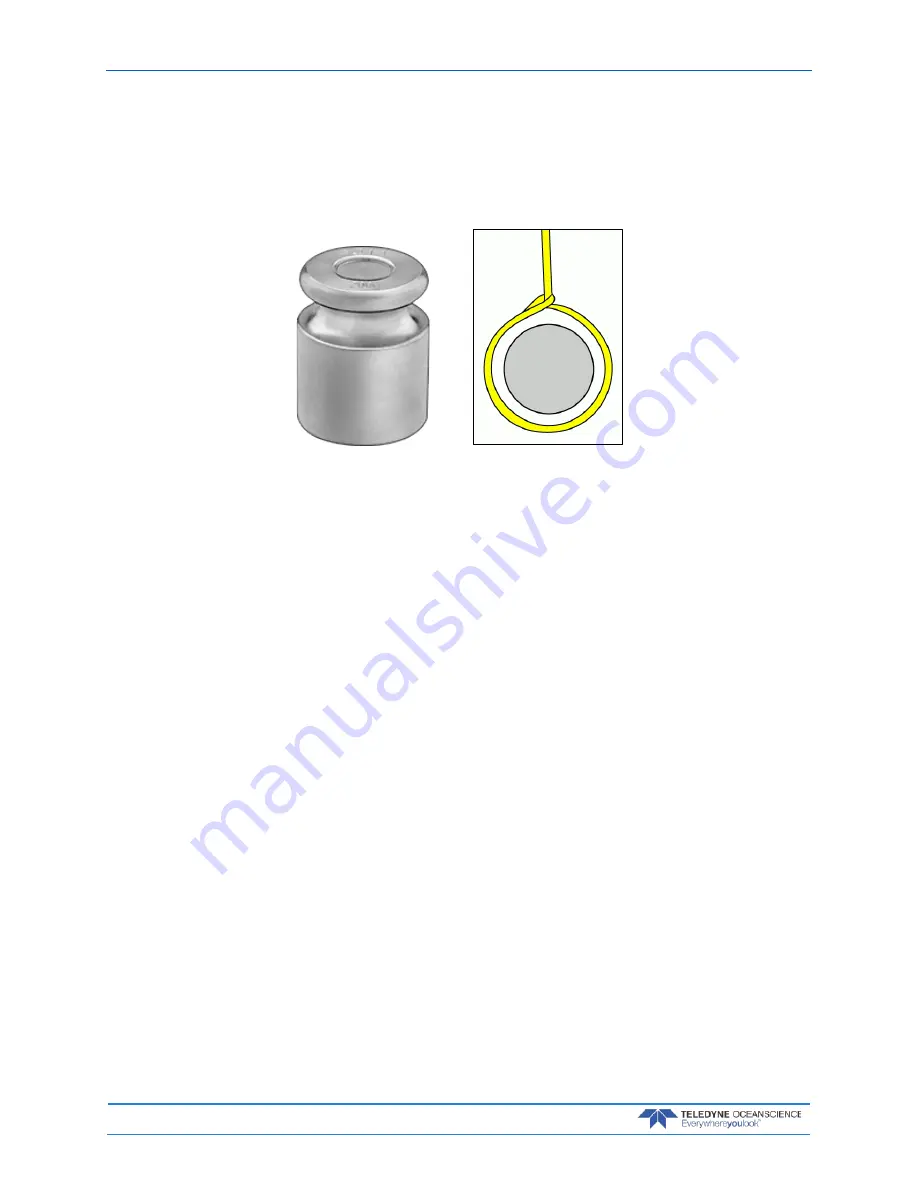
5. Ensure that the line is routed through the LevelWind, Tension Arm, and Davit Pulley exactly as it
would be during normal operation. Choke the line around the provided 200 gram calibration
weight as shown below and allow it to hang freely.
6. Tug on the line to create excess tension, and then gently release the line so that the calibration
weight gradually settles into its free-hanging position. Under Tension-Arm Setpoint Position,
click the Capture button to record the arm’s position. This will set the line tension for Tension-
Controlled Payout.
7. If you are satisfied with the captured positions, click the Apply button to commit these settings to
the Control Module. If you are unsatisfied, you may repeat the capture process as many times as
desired, or you may cancel the calibration simply by closing the Calibration Window. Once a new
calibration has been applied, the settings are stored in the Control Module’s flash memory. A copy
of the calibration file is also stored locally on the PC, as a backup in case the Control Module is
unable to access flash.
8. Cycle power to the winch controller; Make sure that the Calibration Source reads Winch
Controller (see Figure 39, page 71). Upon power cycling, the controller first checks the internal
source of the calibration which is the FLASH card and this is signified by the Winch Controller
source.
If the winch controller fails to find the FLASH stored values, then it reads the temporary file from
the local computer and displays PC as the source, indicating that there is a problem with the
FLASH card, the FLASH is not properly seated, the FLASH is missing, or there is a problem with
the CPU assembly.


