UM_NBASE-T_C
OLOUR
REV.E
09/2018
P
A G E
|
37
7.6
Enhanced Features Control
7.6.1
Rotary Encoder, Rescaler and Frame Delay
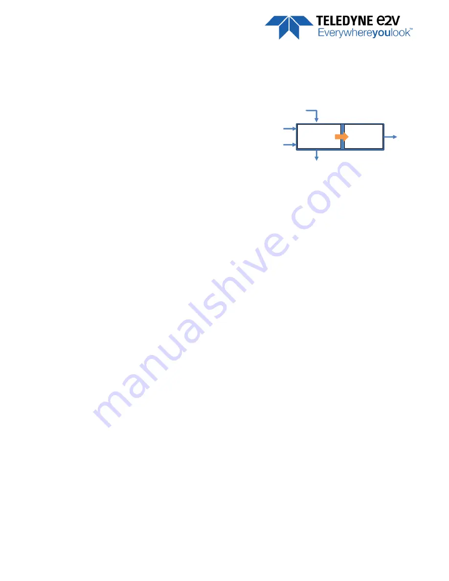
The Embedded Rotary Encoder is managed by the two inputs Lines :
LT1 taken as “A” quadrature input
LT2 taken as “B” quadrature input
The Encoder takes in account the Forward/Reverse indication
given to the camera (by software or external input) to determine
the forward or Reverse position of the A and B quadrature inputs.
Its “Forward/Reverse” outputs is just an indication of its working
mode as soon as it is not disabled but has no action on the
camera scanning direction.
The Output of the Rotary Encoder enters a Rescaler (Multiplier / Divider) that can be also bypassed (neutral).
The Rotary encoder has two working modes :
Quadratic without miscount : The Encoder is sending only forward lines. Any reverse line is not sent and
not counted.
Quadratic with miscount : The Encoder is sending only forward lines but reverse lines are miscount in an
internal counter. The Encoder will restart sending Line triggers as soon as each reverse Line miscounted
has been recounted forward.
The Rotary Encoder can be bypassed. Then the “B” input is disabled and the Line Trigger 1 (LT1) connected on
input “A” is passing through the Rotary encoder to enter the Rescaler
The Rotary encoder can’t be used by changing the camera operation (Forward/Reverse) “on the fly” as some
sensor modes require some reset and some time to change the scanning direction.
Rotary
Encoder
Rescaler
LT1
“A”
LT2
“B”
Mode
F/R
RO


