30
Teledyne API T500U CAPS NO
2
Analyzer with NumaView™ Software
083730510A DCN8172
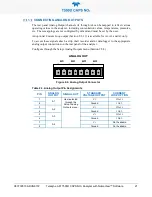
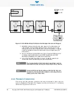
Analyzer
Analyzer
Analyzer
Last Analyzer
Female DB9
Male DB9
RS-232
COM2
RS-232
COM2
RS-232
COM2
RS-232
COM2
Host
RS-232 port
Ensure jumper is
installed between
JP2 pins 21
↔
22 in
last instrument of
multidrop chain.
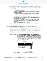
Figure 2-12. RS-232 Multidrop PCA Option Host/Analyzer Interconnect Diagram
7. BEFORE communicating from the host, power on the instruments and
check that the user-selectable Instrument ID is unique for each: in the
Setup>Vars menu, check Instrument ID in the list of variables. To change,
select the variable and press the Edit button; once changed, press the
Enter button.
8. Next, in the Setup>Comm>COM1 menu (do not use the COM2 menu for
multidrop), use the Edit button to set COM1 Quiet Mode and COM1
Multidrop to ENABLED; then press the Accept button.
9. Also check the COM1 Baud Rate to ensure it reads the same for all
instruments (edit if needed and press the Accept button).
Note
The (communication) Host instrument can address only one
instrument at a time, each by its unique ID (see step 7 above).
Note
Teledyne API recommends setting up the first link that runs
between the Host and the first analyzer, and testing it before
setting up the rest of the chain.
P
NEUMATIC
C
ONNECTIONS
This section provides pneumatic connection and setup instructions for basic and valve
option configurations. Pneumatic flow diagrams are shown in Section 2.3.3. Calibration
instructions are provided in Section 4.
Содержание T500U
Страница 2: ......

