


Page 61
Telect, Inc. • USA +1.509.926.6000 • 52.33.3836.37.52
www.telect.com • © 2011 Telect, Inc., All Rights Reserved, 139249-1 A0
ALERT
!
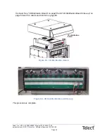
ALERT! When closing the front door of the enclosure, make sure that the top of the door
sits tightly against the frame before tightening the latch; otherwise, a gap could allow wa-
ter entry between the top of the cabinet and the door.
Before you leave the site, check the cabinet to make sure the door is properly closed.
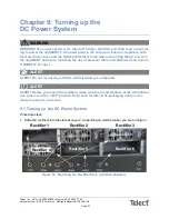
10.3 Turning up the Enclosure
Procedure steps:
1. Turn on the AC service breaker.
2. Make sure the AC voltage at the AC power block is 240V.
3. Turn on one rectifier circuit breaker at a time. Allow a time delay of up to 30 seconds before
the fans start, the green LED comes on, and the yellow, blinking LED goes off. Repeat for
each rectifier.
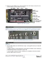
4. Check that the supervisory module has powered up and that the green Power On LED on the
supervisory module LCD display is on.
5. When all the rectifier lights are green, the Heat Exchanger LEDs should all be green. The TE
cooler, fans, and DAC system turn on only when the temperature is approximately 77
o
F
or higher.
6. If the Controller LED screen shows alarms, ignore them at this stage.
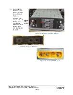
7. Check the DC output voltage and polarity of the battery string(s). Using a voltmeter, connect
the positive (+) probe to the positive (+) terminal and the negative (-) probe to the negative
(-) terminal. If your voltmeter is reading a POSITIVE value of at least 42V, you are fine. If your
voltmeter is reading any negative number, check the connections on your battery string. If the
reading is significantly less than 42V, check the manufacturer’s instructions.
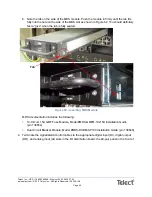
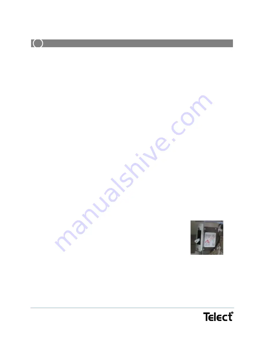
8. Turn on the Battery Disconnect Breaker.
9. Repeat steps 7 and 8 for the second battery string.
10. Check the the Controller LED screen to confirm that the Battery
Fuse Fail alarm clears.
11. Switch on the first load circuit breaker.
12. Check that the connected equipment powers up.
13. Repeat steps 11 and 12 until all the load circuit breakers are on.
14. Check the Controller LED screen to make sure the Load Fuse Fail
alarm has cleared.
15. Check the rectifier currents. Make sure that the load current is representative of what the load
and battery draws.
Figure 66 - Battery
Disconnect Breaker


