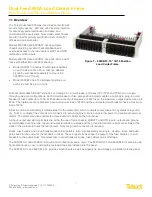
Dual-Feed 600A Load Center Frame
600CB10 & 600CB12 Installation Guide
8
© Telect, Inc. All rights reserved. 7.14.17 136429-2
509.926.6000 :: www.telect.com
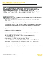
ALERT! Only use components and crimping tools approved by agencies or certifying bodies recognized in your
country or region such as Underwriter’s Laboratories (UL), TUV, etc.
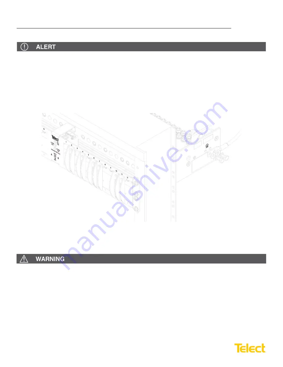
5. Use an approved crimping tool to attach approved, dual-hole compression lug onto suitable grounding wire.
(Size of ground depends on input interruption device.)
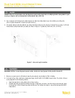
6. If required, lightly coat antioxidant on lug and grounding surface on side of panel. Connect the lug using
1
/
4
-20 bolts,
flat washers and split washers provided, as shown in Figure 7. Tighten the bolt to 50-in./lb. (5.5 N
•
m).
WARNING! Before connecting input power cables, make sure input power to the panel is turned off.
7. Make sure input power is off before connecting the panel’s input cables to PDU or battery.
8. For input wiring, crimp dual-hole compression lugs onto #1 AWG to 750 MCM copper wires. The choice of input
wiring depends on the following criteria:
•
Input interrupt device rating affects size of input wiring.
•
Ambient operating temperature affects the type of input wire insulation. Use the table on the following page
to choose the correct temperature-rated input wires. For further information, consult the National Electrical
Code (NEC).
Figure 7 – Ground Lug Connection


