safe
smart
strong
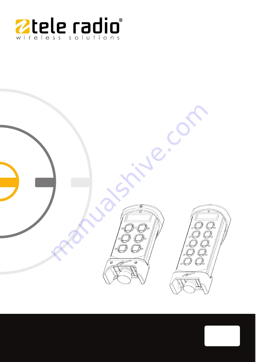
T 9
T 1 1
T9-02, T9-12
T11-04, T11-14
END USERINSTRUCTIONS
Transmitters:
ED-TG2-TX102-EN-v02
Language: English (original)
Страница 1: ...safe smart strong T 9 T 1 1 T9 02 T9 12 T11 04 T11 14 END USER INSTRUCTIONS Transmitters ED TG2 TX102 EN v02 Language English original...
Страница 2: ...Tele Radio AB Datav gen 21 SE 436 32 Askim Sweden Phone 46 0 31 748 54 60...
Страница 3: ...Top LED status indication 18 5 2 Error indications and messages 18 CHAPTER 6 OPERATION 19 6 1 General information 19 6 2 General navigation 19 6 3 User permissions 20 6 4 Functionality test 21 6 5 Sta...
Страница 4: ...End user instructions T9 T11 10 3 AEC 39 ANNEX A INDEX 40 4 ED TG2 TX102 EN v02...
Страница 5: ...s and should not be used for this purpose It is the responsibility of any such users or integrators to perform the appropriate and complete risk analysis evaluation and testing of the products with re...
Страница 6: ...tions T9 T11 Chapter 1 Introduction Tele Radio AB products are covered by a warranty against material construction or manufacturing faults See Chapter 9 Warranty service repairs and maintenance 6 ED T...
Страница 7: ...No part of this publication may be reproduced stored in a retrieval system or transmitted in any form or by any means electronic photographic mechanical including photocopying recording or otherwise f...
Страница 8: ...and electric hoists or mobile applications 1 2 1 AB OUT T9 T11 TRANSMI TTERS T9 T11 transmitters have simplex communication with support for duplex T9 T11 transmitters are compatible with all R4 R9 a...
Страница 9: ...he appropriate training The purchaser of this product has been instructed how to handle the system safely The following information is intended for use as a complement to applicable local regulations...
Страница 10: ...tter unattended l Always switch the transmitter off when not in use Store in a safe place l Keep a clear view of the work area at all times 2 1 2 MAI NTENANCE Before maintenance intervention on any re...
Страница 11: ...product although the encapsulation or foil is damaged moisture can cause serious damage to the electronics 2 2 Safety features 2 2 1 STOP B UTTON Tele Radio AB transmitters are equipped with a stop b...
Страница 12: ...125 926 9875 Number of channels 69 channel 1 69 69 channel 1 69 Number of frequency banks 15 bank 1 15 15 bank 1 15 Radio frequency output power EIRP1 10 dBm 10 mW EIRP 0 dBm 1 mW EIRP 10 dBm 10 mW EI...
Страница 13: ...34 375 04 433 150 29 433 775 54 434 400 05 433 175 30 433 800 55 434 425 06 433 200 31 433 825 56 434 450 07 433 225 32 433 850 57 434 475 08 433 250 33 433 875 58 434 500 09 433 275 34 433 900 59 434...
Страница 14: ...pping spread spectrum FHSS to communicate The frequency band is divided into 15 frequency banks 1 15 Frequency bank 1 is selected by default To establish a radio link between the receiver and the tran...
Страница 15: ...strative purposes only 4 1 Transmitter front T9 02 T9 12 T11 04 T11 14 1 Rubber cover 2 Top LED 3 LCD display 4 Button 1 5 Button 2 6 Button 3 7 Button 4 8 Left Start button1 9 Right Start button2 10...
Страница 16: ...Y The I O switch on the back of the transmitter interrupts the power supply from the battery When in the O off position the transmitter cannot be started unless the charger plug is connected IMPORTANT...
Страница 17: ...smitter display is controlled by the transmitter s joystick and side buttons 1 Radio communication Simplex Duplex 2 Signal strength 3 Channel number 4 Operating frequency 5 Battery level indication1 4...
Страница 18: ...ttery capacity is good and red when the battery capacity is poor When the top LED lights flashes red battery should be charged or changed at the next convenient opportunity see 7 2 2 Charge the batter...
Страница 19: ...the receiver proceed with the login procedure before using the system Once a transmitter has been logged in it will remain logged in until it is manually logged out More than one transmitter can be r...
Страница 20: ...Accept the updated value 3 4 Move between the digits 1 2 Increase decrease the value displayed 6 3 User permissions Setting protection or Start up protection can be activated to prevent unauthorized...
Страница 21: ...ing steps l Make sure that the controlled object can not cause any harm in the event of unexpected movement l Always follow local safety rules and start the equipment according to the corresponding in...
Страница 22: ...d the next time the transmitter is started 1 Make sure that the Stop button is pressed 2 Twist and release the Stop button The top LED lights The receiver s selected in the last session are indicated...
Страница 23: ...ing and remains lit the selected receivers red LEDs go out and the stop relays activate 6 Proceed with the functional test see 6 4 Functionality test If not successfully completed the display will sho...
Страница 24: ...ction is taken within 3 minutes after the Stop button has been released the transmitter will turn off Press the Stop button before making a new attempt to start the transmitter NOTE The last accessed...
Страница 25: ...essing 5 6 T11 The display shows Start by pressing 9 10 To cancel press the same button again 5 Press and hold both Start buttons simultaneously The buzzer emits a beep 6 Release both Start buttons Th...
Страница 26: ...o session 6 7 1 QUI CK LOGOUT 1 Make sure that the transmitter is started If not twist and release the Stop button 2 Press and hold the left Start button 1 3 Press the Stop button The top LED lights r...
Страница 27: ...rect type l Do not short circuit disassemble deform or heat batteries l Never attempt to charge a visibly damaged or frozen battery l Do not use or charge the battery if it appears to be leaking defor...
Страница 28: ...ltiple batteries in the same plastic bag l Do not incinerate or dispose of batteries in fire l Do not place used batteries in the household waste Dispose of used batteries in accordance with the appli...
Страница 29: ...rgeable lithium ion battery Article number M245060 Operating time 16 h with continuous usage Charge Charger plug on the back of the transmitter Charger plug on the back of the transmitter or Charger u...
Страница 30: ...se a screwdriver to remove the screws in the back of the transmitter 4 Gently pull to release the back encapsulation black 5 Remove the back encapsulation by hand 6 Turn it over so the circuit board i...
Страница 31: ...red and the internal buzzer beeps 3 times 2 Lift the protection cap and insert the charger plug into the socket on the back of the transmitter The top LED flashes red while the battery is charging If...
Страница 32: ...e battery is fully charged Charger unit The charger s LED turns green when the battery is fully charged 4 Remove the charger plug and close the protection cap For external batteries remove the battery...
Страница 33: ...temperature range is 21 C to 38 C 70 F to 100 F l Initial tape application to surfaces at temperatures below 10 C 50 F is not recommended because the adhesive becomes too firm to adhere readily Howev...
Страница 34: ...llowing are not covered by the warranty l Faults resulting from normal wear and tear l Parts of a consumable nature l Products that have been subject to unauthorized modifications l Faults resulting f...
Страница 35: ...lete EU Declaration of Conformity is available on the Tele Radio AB website www tele radio com 10 1 2 WEEE DI RECTI VE This symbol means that inoperative electrical and electronic products must not be...
Страница 36: ...nstructions may cause harmful interference to radio communications However there is no guarantee that interference will not occur in a particular installation If this equipment does cause harmful inte...
Страница 37: ...tout brouillage radio lectrique subi m me si le brouillage est susceptible d en compromettre le fonctionnement To satisfy IC RF exposure requirements a separation distance of 20 cm or more should be m...
Страница 38: ...NFC1108B Contains IC 4807A C1108B Or ou Contains FCC ID ONFC1203B Contains IC 4807A C1203B 10 2 3 FCC I C LAB ELS The radio module in this product is labeled with its own FCC ID and IC numbers The FCC...
Страница 39: ...Chapter 10 Regulatory information 10 3 AEC Applies to n T9 02 n T11 04 10 3 1 AEC STATEMENT This product is declared as compliant within Eurasian Economic Union EAC EAC declaration is available on re...
Страница 40: ...9 Charge 31 Removal of internal battery 30 Battery precautions 27 Handling 27 Storage 27 C Charging temperature 12 29 D Dimensions 12 Display specifications 12 Disposal 28 F FCC statement 36 FCC IC la...
Страница 41: ...12 Number of frequency banks 12 O Operating temperature 12 Operating time 12 P Power supply 12 R Radio communication 12 Radio frequency band 12 433 MHz 13 915 MHz 14 Frequency channels 13 Radio freque...
Страница 42: ...N code 24 Stop button 11 Storage temperature Battery 29 Switch off 26 T Top LED 17 18 Transmitter back 16 Transmitter display 17 Transmitter front views 15 U User permission 20 W Warnings restrictions...
Страница 43: ...End user instructions T9 T11 This page intentionally left blank ED TG2 TX102 EN v02 43...
Страница 44: ...safe smart strong These End user instructions are subject to change without prior notice Download the latest End user instructions from www tele radio com...