


Removal and Installation Procedures
6- 36
TDS6000 Series Service Manual
a.
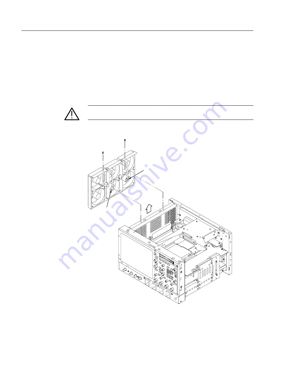
Disconnect the fan from the processor/display board:
Disconnect the two
fan power cables J130 and J170 located on the processor board.
b.
Remove the two T-15 Torxdrive screws securing the fan assembly to the
top main chassis.
c.
Lift the fan assembly up and out from the chassis.
4.
Reinstallation:
Do in reverse steps a through c to reinstall the fan assembly.
CAUTION.
Take care when handling the fan assembly, the fan blades are brittle
and can be easily damaged.
Disconnect
from J130
Disconnect
from J170
Figure 6- 21: Fan assembly removal
Содержание TDS6404
Страница 4: ......
Страница 14: ...Table of Contents x TDS6000 Series Service Manual...
Страница 18: ...Service Safety Summary xiv TDS6000 Series Service Manual...
Страница 52: ...Operating Information 2 12 TDS6000 Series Service Manual...
Страница 56: ...Theory of Operation 3 4 TDS6000 Series Service Manual...
Страница 60: ...Performance Verification 4 4 TDS6000 Series Service Manual...
Страница 84: ...Performance Tests 4 28 TDS6000 Series Service Manual...
Страница 150: ...Adjustment Procedures 5 2 TDS6000 Series Service Manual...
Страница 156: ...Maintenance 6 6 TDS6000 Series Service Manual...
Страница 170: ...Removal and Installation Procedures 6 20 TDS6000 Series Service Manual...
Страница 228: ...Repackaging Instructions 6 78 TDS6000 Series Service Manual...
Страница 232: ...Options 7 4 TDS6000 Series Service Manual...
Страница 234: ...Electrical Parts List 8 2 TDS6000 Series Service Manual...
Страница 252: ...Mechanical Parts List 10 16 TDS6000 Series Service Manual...


