8. The System badges show global instrument settings (Horizontal, Trigger, Acquisition, Run/Stop status, and Date/Time).
on page 22.
9. The Inactive Channel buttons add channel waveforms to the Waveform view and add an associated Channel badge to the
Settings bar.
The Add Math Ref Bus button expands allowing you to add a math, reference, or bus waveform to the Waveform view and
add an associated Waveform badge to the Settings bar.
The RF button activates the frequency domain display and adds an RF badge. Double-tap the badge to open the RF
configuration menu to configure the RF input. This button is only active if one of the RF options is enabled.
The AFG button opens the AFG configuration menu to set and enable the AFG output. This button is only present if the
AFG option is installed.
The DVM button lets you use an analog probe to take DC, AC RMS, or DC+AC RMS voltage measurements on your DUT.
Tap the button to add a DVM badge to the Results Bar and open a configuration menu. The DVM option also enables a
trigger frequency counter, accessible from the Mode & Holdoff panel in the Trigger badge menu. This button is only
present if the DVM option is installed.
10. Double-tap a badge to open its associated configuration menu. See
page 27.
If you add more Channel or Waveform badges than can fit in the waveform badge display area, tap the scroll buttons at
each end of the waveform badge area to scroll and display hidden badges.
11. The Waveform Handles on each waveform identify the source of that waveform (Cx for channels, M for Math, Rx for
Reference waveforms, Bx for bus waveforms). The waveform handles are at the zero-volt level of the waveform by default.
The currently selected waveform handle is a solid color; unselected waveform handles are outlined.
Double-tapping a waveform handle opens the configuration menu for that waveform.
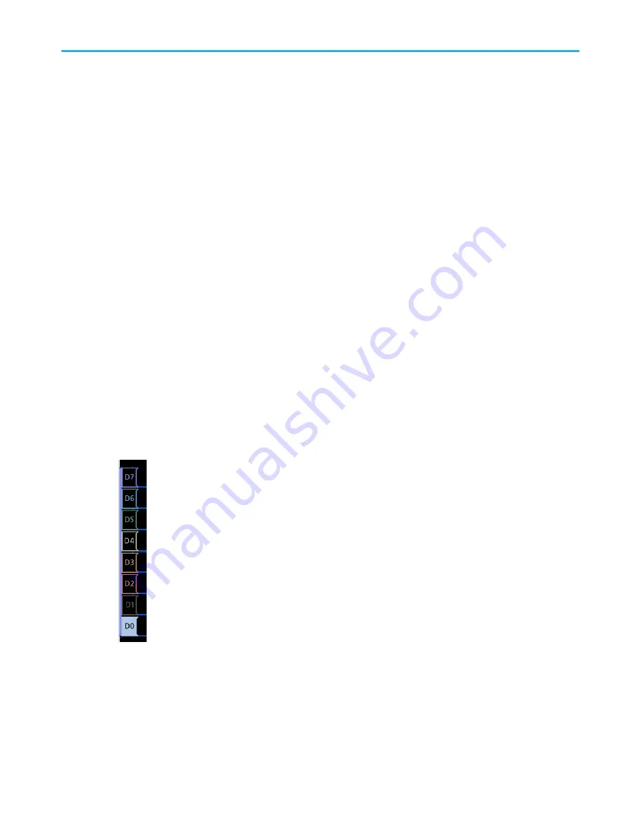
For digital channels, the waveform handle shows the channel number, with each individual digital signal labeled D0–D15
and displayed with a different color.
Double-tapping a digital waveform handle opens the digital channel configuration menu.
Dragging a digital signal handle over another handle swaps location of the signals in the waveform view. Dragging a digital
signal handle out of the group, creates a new group. A selected digital group or signal handle can be moved using the
Vertical Position control.
Getting acquainted with your instrument
MDO32, MDO34 Installation and Safety Manual
19
ООО "Техэнком" Контрольно-измерительные приборы и оборудование www.tehencom.com
Содержание MDO3 Series
Страница 18: ...Installing your instrument 8 MDO32 MDO34 Installation and Safety Manual www tehencom com...
Страница 40: ...Getting acquainted with your instrument 30 MDO32 MDO34 Installation and Safety Manual www tehencom com...
Страница 46: ...Configure the instrument 36 MDO32 MDO34 Installation and Safety Manual www tehencom com...
Страница 50: ...EMC safety and environmental compliance 40 MDO32 MDO34 Installation and Safety Manual www tehencom com...


