Installing Devices 6-9
6.8
Installing Solid State Disks
The TEK-AT4L
PLUS
Single Board Computer supports 2, 4 or 8MB Flash EPROM Disk.
The Flash EPROM is surface mounted component option which must be sized and
ordered by the customer.
6.8.1
Writing To Flash Disks
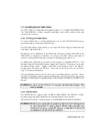
To create a Flash disk (i.e. writing information to it), use the XFLASH utility found on
the utilities diskette which came with the board.
The XFLASH software utility allows you to choose files from floppy and hard disks and
write them to the Flash disks.
Information can be transferred to the Flash disk by directly running XFLASH on the
TEK-AT4L
PLUS
computer, or remotely - by using a serial link. The second option is
referred to as Download Mode and is enabled by installing jumper SW1(7-8).
In addition, the Flash disk can be made to boot simply by installing SW1(1-2). This
function causes the Flash disk to replace floppy disk 0 from the "A" position - leaving the
mechanical floppy unused. Floppy 0 must then be physically moved to the floppy 1
position where it becomes the "B" drive. Please refer to the
Physical Devices Table
(see
Page 5-7) for more information.
The only difference between the two drive types is that Flash disks are read only. Hence,
whenever an attempt is made to write to the Flash disk, a write-protect error is generated.
Writing to Flash disks is explained below and in detail in Teknor's
XFLASH User's
Manual
.
WARNING:
In order for the AT4L
PLUS
to recognize the Flash disk, Jumper W14
must be installed.
6.8.2
SRAM Disk
The TEK-AT4L
PLUS
supports from 512KB to 2MB SRAM. The SRAM is surface
mounted component option which must be sized and ordered by the customer.
Please refer to Section 9 -
Setting Jumpers
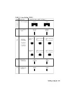
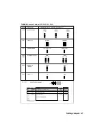
to enable SRAM on the board (if installed).
WARNING:
SRAM power consumption is usually less than 5mA in 3V backup mode.
So files transferred to battery-backed SRAM disks typically stay
resident for two years. Actual life, however, is dependent on the actual
consumption of the SRAM devices installed.
Содержание TEK-AT4L Plus
Страница 7: ...PRODUCT DESCRIPTION 1 PRODUCT OVERVIEW 2 ONBOARD SUBSYSTEMS...
Страница 9: ...Product Overview 1 2 TEK AT4LPLUS Block Diagram...
Страница 26: ...Installing Devices 6 3 CONNECTOR LOCATION...
Страница 35: ...Setting Jumpers 8 3 JUMPER LOCATIONS...
Страница 36: ...Setting Jumpers 8 5 TABLE 8 1 Jumper Settings W1 W11...
Страница 37: ...Setting Jumpers 8 6 TABLE 8 2 Jumper Settings W12 W19 W26...
Страница 38: ...Setting Jumpers 8 7 TABLE 8 3 Jumper Settings W20 W25 SW1 SW2...
Страница 41: ...APPENDICES A PRODUCT SPECIFICATIONS B BOARD DIAGRAMS C CONNECTOR PINOUTS...
Страница 43: ...Board Diagrams B 1 B 1 TEK AT4LPLUS Assembly Diagram Top View...
Страница 44: ...Board Diagrams B 3 B 2 TEK AT4LPLUS Mounting Holes...
Страница 45: ...Board Diagrams B 5 B 3 TEK AT4LPLUS Mechanical Specifications...


