Installing Devices 6-1
6. INSTALLING DEVICES
6.1 Connecting Power Supply
Power can be drawn on the TEK-AT4L
PLUS
using the onboard power connector (J5), or
the ISA-AT bus power capabilities when the board is connected in a backplane.
WARNING
: Both power supply must not be connected together. While using one, the
other must be disconnected.
6.1.1
Supplying Power Using the ISA-AT Bus
+5V, -5V, +12V, -12V and ground voltages are routed on the edge connector as follows:
Note:
The complete description of the edge connector is given in the appendix E
- Board Connectors and Pinout
.
6.1.2
Supplying Power Using the Power Connector
(J5)
The Power Supply is drawn on the Backplane using the 6-pin J5 connector.
Содержание TEK-AT4L Plus
Страница 7: ...PRODUCT DESCRIPTION 1 PRODUCT OVERVIEW 2 ONBOARD SUBSYSTEMS...
Страница 9: ...Product Overview 1 2 TEK AT4LPLUS Block Diagram...
Страница 26: ...Installing Devices 6 3 CONNECTOR LOCATION...
Страница 35: ...Setting Jumpers 8 3 JUMPER LOCATIONS...
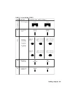
Страница 36: ...Setting Jumpers 8 5 TABLE 8 1 Jumper Settings W1 W11...
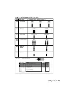
Страница 37: ...Setting Jumpers 8 6 TABLE 8 2 Jumper Settings W12 W19 W26...
Страница 38: ...Setting Jumpers 8 7 TABLE 8 3 Jumper Settings W20 W25 SW1 SW2...
Страница 41: ...APPENDICES A PRODUCT SPECIFICATIONS B BOARD DIAGRAMS C CONNECTOR PINOUTS...
Страница 43: ...Board Diagrams B 1 B 1 TEK AT4LPLUS Assembly Diagram Top View...
Страница 44: ...Board Diagrams B 3 B 2 TEK AT4LPLUS Mounting Holes...
Страница 45: ...Board Diagrams B 5 B 3 TEK AT4LPLUS Mechanical Specifications...


