Chapter 9 Expansion Module
222
4)
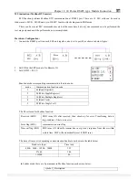
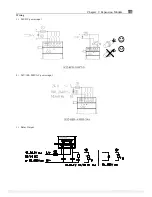
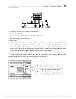
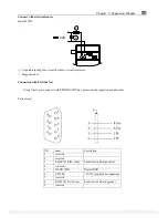
Transistor output
+
+
-
SG2-8ET-D
+
OUTPUT 4 x TR/0.5A
-
+
-
-
Y1
Y2
Y3
Y4
①
-1A quick-blowing fuse, circuit-breaker or circuit protector
②
-Surge absorber (43V DC)
③
-Surge absorber (Input 24VAC:43V; Input 100~240VAC:430V AC)
④
-Fuse, circuit-breaker or circuit protector
⑤
-Inductive load
※
AC inductive load needs to connect Surge absorber in parallel way to absorb the noise if the SG2 output
terminal is the relay type. DC inductive load needs parallel connect commute diode if the SG2 output terminal is
the relay type. The specification of inverse voltage for commute diode should be more than 5~10 times the rated
current of the circuit, and the specification of positive current of diode should be more than load current.
Inductive load needs parallel connect commute diode if the SG2 output is transistor.
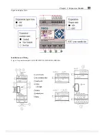
Digital IO module and Analog module both have indicator light in orange color. The state of indicator light in
different operation state is the same. The state of indicator light is shown below.
Running status of expansion module
Flick (3Hz), expansion module is fault
-
data transfer error
-
connecting is error with module before
PDF compression, OCR, web optimization using a watermarked evaluation copy of CVISION PDFCompressor


