Chapter 5 Relay Ladder Logic Programming
68
-
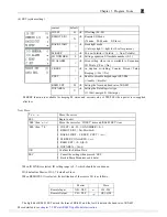
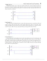
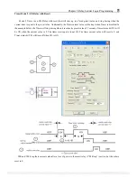
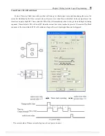
Auxiliary Coils ( N )
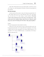
The function of auxiliary coils, N, is the same as auxiliary coils M, but it can’t be kept when the smart powers
down. In the first rung of this example, auxiliary relay N01 is being used as an output coil and will be energized when
input I03 turns on. In the second rung auxiliary relay N01 is being used as an input, and outputs Q04 and Q05 will be
turned ON once N01 is conducted.
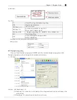
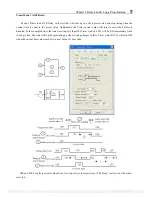
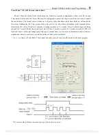
Timer Elements ( T )
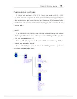
Timer coil provides the relationship between its current value and the preset value of a selected timer. The timer
contacts will turn on when the current value is equal or greater than the preset value of a selected timer. In this
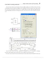
example, when input I03 turns on, timer T01 will start. When the timer reaches the preset of 5 seconds, timer status
contact T01 turns on. When T01 turns on, output Q04 will turn on. Turning off I03 will reset the Timer.
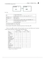
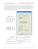
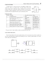
Counters Elements ( C )
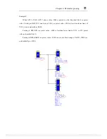
Counter coil provides the relationship between its current value and the preset value of a selected counter. The
counter contact will turn on when the current value is equal or greater than the preset value of a selected counter. In
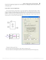
this example, each time the input contact I04 changes its state from off to on, the counter (C01) increments by one.
When the counter value reaches the preset value, 2, the counter status contact C01 turns on. When C01 turns on,
output Q05 will turn on. When M02 turns on counter C01 will reset. If M09 is turned on, the counter will change
from a count-up to a count-down counter.
PDF compression, OCR, web optimization using a watermarked evaluation copy of CVISION PDFCompressor

