Chapter 6 FBD Block Diagram Programming
145
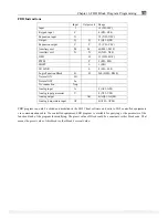
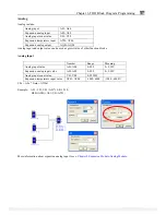
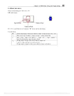
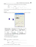
Logic Block Instructions
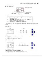
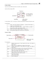
Logic blocks display in FBD:
Press the button:
→
Move cursor: input terminals
①
→
Logic block number
③
→
display next
connected block or coil
←
Move cursor: Logic block number
③
→
input terminals
①
→
Logic/Function display (input terminal is block)
↑
↓
Move cursor up or down (when multiple input terminals)
※
Logic Block include: AND, AND EDGE, NAND, NAND EDGE, OR, NOR, XOR, NOT, RS, PULSE,
BOOLEAN.
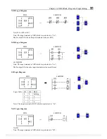
AND Logic Diagram
FBD:
LADDER:
=
I01 And I02 And I03
Note: The input terminal is NOP which is equivalent to ‘‘Hi”;
The B output ON when all input terminals status are ON;
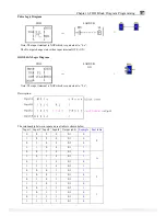
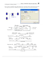
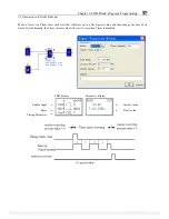
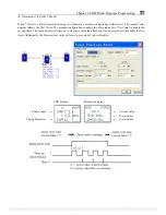
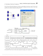
AND (EDGE) Logic Diagram
FBD:
LADDER:
=
I01 And I02 And I03 And D
Note: The input terminal is NOP which is equivalent to ‘‘Hi”;
The B output ON a scan cycle time when all input terminals status are ON;
PDF compression, OCR, web optimization using a watermarked evaluation copy of CVISION PDFCompressor


