


CAN UP 27 installation / Configuration of CAN UP 27 / Interface of Service CAN UP software
CAN UP 27 online telematics gateway. Operation manual. Version 1.0
© Technoton, 2017
27
2.4.2 Interface of Service CAN UP software
Service CAN UP software is launched with
desktop shortcut created during installation.
Software interface consists of
Horizontal menu
,
Vertical menu,
Unit
ID area
and
Information and Configuration area
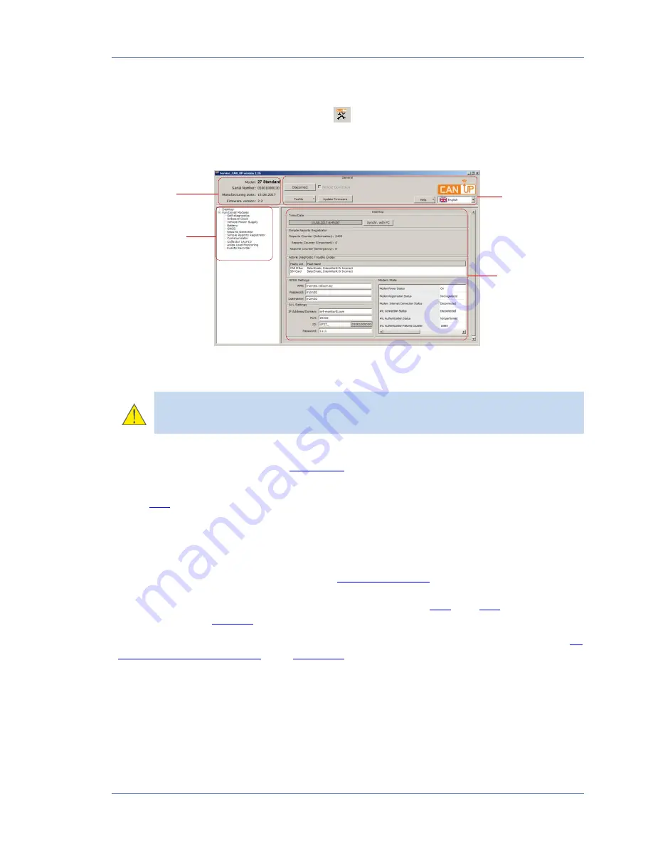
(see figure 11)
Figure 11 — Interface of Service CAN UP
ATTENTION:
At
lower
screen
resolutions
(less
than
1024x768)
Service CAN UP window is automatically set to full screen. In this case scroll bars
are used to display unseen areas.
Unit ID area
provides information about the model, serial number, manufacturing date and
firmware version of the connected
CAN UP 27
.
Horizontal menu
provides the following:
Unit
is connected/disconnected;
Profile options (loading profile, saving profile, and printing profile);
Firmware update;
Selection of interface language;
Help and Information about the manufacturer.
Vertical menu
is used for selection of
Function modules
of CAN UP 27.
Its current
parameters and configuration are displayed in
Configuration and Information area
.
Function modules of Service CAN UP software are based on
PGN
and
SPN
messages from
S6
Database
(see
annex C
).
The detailed description of S6 Database can be found in the web-pages
S6
(
http://s6.jv-technoton.com/
) part
Data Base
.
Information and Configuration
area displays names (PGN) and parameters (SPN) of the
messages. Each SPN holds the following: data range, discretion, measuring units.
Horizontal
menu
Information and
configuration area
Unit ID area
Vertical menu


