background image


TECNOLOGIC spa - TLK 43


- OPERATING INSTRUCTIONS - Vr.02 - ISTR 06267 - PAG. 9


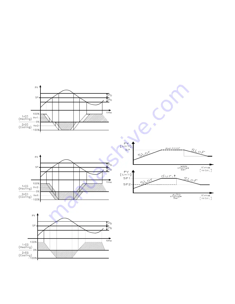
The use of this function is only possible if the PID control is dual 
function and can be used to delay or bring forward the intervention 
of the actuators commanded by the instrument. 
Using this function it is therefore possible to optimise the 
intervention of the two actuators in such a way that their actions do 
not overlap or so that they overlap so that they obtain the mix of the 
two actions of the actuators. 
Basically, this means setting two power offsets (one for direct action 
and one for reverse action) that set the beginning of the intervention 
of the actuator commanded by the output. 
The parameters that can be set for this function contained in the 
block 

]

rEG”,

 are: 

“thr1”

 : Power threshold at which output 1rEG begins to operate. 

“thr2”

 : Power threshold at which output 2rEG begins to operate. 

Basically, if one wishes to bring forward the reverse action (1rEG) 
and delay the direct action (2rEG) it is necessary to set positive 
values on parameter “thr1” and negative values on parameter “thr2”. 
In this way, the area within which the two outputs are not activated 
at the same time is increased. 


Vice versa if one wishes to extend the reverse action (1rEG) and 
bring forward the direct action (2rEG) it is necessary to set negative 
values on parameter “thr1” and positive values on parameter “thr2”. 
In this way, the area within which the two outputs are activated at 
the same time is increased. 


The split range function is deactivated by setting the respective 
parameters =0.


note

 : In order to simplify the explanation of the example graphs a  

dual action control that is only proportional (and therefore with “dEr”  
and “Int” = OFF)  with “Prat” = 1.0 and “rS” = 0.0 was considered. 
 

4.12 - REACHING OF THE SET POINT AT CONTROLLED SPEED 
AND AUTOMATIC SWITCHING BETWEEN TWO SET POINTS 
(RISE RAMP, FALL RAMP AND DWELL TIME)


All the parameters referring to the ramps functioning are contained 
in the group 

]

rEG”.


It is possible to reach the set point in a predetermined time (in any 
case longer than the time the plant would naturally need). This could 
be useful in those processes (heating or chemical treatments, etc.) 
where the set point has to be reached gradually, in a predetermined 
time. 
Once the instrument has reached the first Set Point (SP1) it is 
possible to have automatic switching to the second Set Point (SP2) 
after a set time, thus obtaining a simple automatic thermic cycle. 
These functions are available for all the programmable controls (PID 
single and double action, ON/OFF and Neutral Zone ON/OFF). 
The function is determined by the following parameters :  

"SLor"

 - Gradient of rise ramp  (Process value < Set point) 

expressed in unit/minute  

"SLoF"

 - Gradient of fall ramp (Process value > Set point) 

expressed in unit/minute. 

"dur.t"

 – Dwell time of Set Point SP1 before automatic switching to 

Set Point 2 SP2 (expressed in hrs. and min.). 
The functions are deactivated when the relative parameters are = 
InF. 
When the Set Point value is changed or at switch on, the instrument 
automatically determines which of the two values “SLor” or “SLoF” it 
has to use.  

Note:

 In case of PID control, if Auto-tuning is desired whilst the 

ramp function is active, this will not be carried out until the tuning 
cycle has been completed. 
It is therefore recommended that Auto-tuning be started avoiding 
activating the ramp function and, once the tuning is finished, 
deactivate Auto-tuning  (“Auto” = OFF), program the desired ramps 
and, if it automatic tuning is desired, enable the Self-tuning function. 


Examples with starts from values lower than SP and with decreasing 
of SP. 
 

4.13 - SOFT-START FUNCTION


All the parameters referring to the Soft -Start functioning are 
contained in the group 

]

rEG”.


The Soft-Start function only works through PID control and allows 
the limitation of control power when the instrument is switched on, 
for a programmable period of time. 
This is useful when the actuator, driven by the instrument, may be 
damaged excess power supplied when the application is not yet in 
the normal rating. (ex. for certain heating elements).  
The function depends on the following parameters : 

 “St.P”

 – Soft-Start power 

“Sst”

 – Soft-Start time (expressed in hh.mm) 

The possible function modes are the following : 

1) 

If both parameters are programmed with values other than OFF, 

when switched on the instrument gives an output power as 
programmed on par. “St.P” for the time programmed on par. “SSt”. 
Practically, the instrument works in manual condition and switches 
to automatic control at the elapsing of time “SSt”. 

Содержание TLK 43

Страница 1: ...also instructions for its maintenance and use we therefore recommend that the utmost attention is paid to the following instructions Though this manual has been issued with the greatest care TECNOLOG...

Страница 2: ...ualized on 4 green displays while the outputs status is indicated by 4 leds The instrument provides for the storage of 4 Set Points and can have up to 4 outputs relay type or can drive solid state rel...

Страница 3: ...e visualised on the SV display by pushing the P key Again by using the UP and DOWN keys it is possible to select the desired parameter and if the key P is pressed the display PV will show the paramete...

Страница 4: ...rogrammed on par SPLL and the one programmed on par SPHL Note in all the following examples the Set point is indicated as SP however the instrument will act according to the Set point selected as acti...

Страница 5: ...positive or negative offset that is simply added to the value read by the probe before visualisation which remains constant for all the measurements If instead it is desired that the offset set should...

Страница 6: ...ameters referring to the ON OFF control are contained in the group rEG This type of control can be obtained by programming par Cont On FS or On FA and works on the output programmed as 1 rEG depending...

Страница 7: ...at Power Ratio or relation between power of the element controlled by output 2rEG and power of the element controlled by output 1rEG 4 7 PID CONTROL FOR MOTORIZED ACTUATORS WITH TIME POSITIONING 1rEG...

Страница 8: ...grammed parameters To make the error ErAt disappear swap the instrument to the OFF control OFF and then turn it to automatic control rEG The Auto tuning cycle duration has been limited to 12 hours max...

Страница 9: ...ents etc where the set point has to be reached gradually in a predetermined time Once the instrument has reached the first Set Point SP1 it is possible to have automatic switching to the second Set Po...

Страница 10: ...band alarm OR MAXIMUM SET OF ALn ALARM THRESHOLD for low or high alarm HALn ALARM HYSTERESIS ALnd ALARM ACTIVATION DELAY in sec ALni ALARM BEHAVIOUR IN THE EVENT OF MEASUREMENT ERROR ALnt ALARM TYPE...

Страница 11: ...larm is active Enter group Hb and program which output the alarm signal has to address on parameter OHb The functioning mode of the alarm is instead defined on par HbF which can be set in the followin...

Страница 12: ...P1 2 By closing the contact connected to the digital input the set point SP2 is selected as being active while opening the contact selects the set point SP1 as active The function can only be activate...

Страница 13: ...l info please have a look at the KEY01 instruction manual 5 PROGRAMMABLE PARAMETERS Here following are described all the parameters available on the instrument Some of them could be not present or bec...

Страница 14: ...2 for high or low alarm AL2L 9999 9999 49 HAL2 Alarm AL2 hysteresis OFF 9999 1 50 AL2d Activation delay of alarm AL2 OFF 9999 sec OFF 51 AL2i Alarm AL2 activation in case of measuring error no yES no...

Страница 15: ...modes of the variable measured by the probe HCFG INPUT TYPE This permits selection of the input type thermocouples tc thermo resistances or thermistors rtd normalized signals in current I in voltage...

Страница 16: ...no_0 if one intends to use the beginning of the scale as being other than 0 4 mA or 2 V Ao1F ANALOGICAL OUTPUT OUT1 FUNCTION This determines the function of the OUT 1 output as control output 1 1 rEG...

Страница 17: ...LARM AL3 Similar to AL1d but referring to alarm AL3 AL3i ALARM AL3 ACTIVATION IN CASE OF MEASUREMENT ERROR Similar to AL1i but referring to alarm AL3 GROUP LbA PARAMETERS RELATIVE TO THE LOOP BREAK AL...

Страница 18: ...tched on the actuator must remain where it is no whether is must be taken to the maximum opening position oPEn or the maximum closing position cLoS Parameters relative to the ramps allowing the Set Po...

Страница 19: ...l stations must have the same transmission speed PACS ACCESS TO PROGRAMMING THROUGH SERIAL PORT Programming access If programmed as LoCL this means that the instrument can only be programmed from the...

Страница 20: ...ature 10 60 C 7 3 MECHANICAL DIMENSIONS PANEL CUT OUT AND MOUNTING mm 7 4 FUNCTIONAL FEATURES Control ON OFF single and double action PID PID for motorized actuators with time positioning Measurement...

Страница 21: ...99 9 999 9 19 99 99 99 1 999 9 999 0 10 V HCFG UoLt SEnS 0 10 1999 9999 199 9 999 9 19 99 99 99 1 999 9 999 2 10 V HCFG UoLt SEnS 2 10 1999 9999 199 9 999 9 19 99 99 99 1 999 9 999 7 6 INSTRUMENT ORDE...

Отзывы: