background image

Page 12 • MN03010 ║ Issue/Rev. 0.4 (6/17)

Model 210 Valve (I / O / S) Manual   


Service and Maintenance


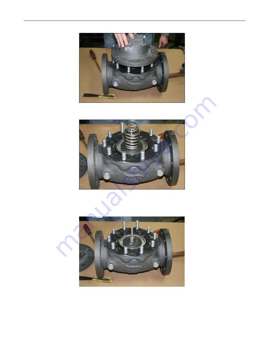
Figure 7

 – Cover Removal


Figure 8

 – Cover Removal


Remove the spring(s) from the valve stem.


Figure 9

 – Cover Spring Removal


Remove the stem assembly from the valve body. On the underside of the stem, note 

that the stem may have a flat machined surface. This flat surface is dependent on 

valve size. Some valve sizes have a nut where this flat would be (Figures 10 and 11). 

Secure this flat surface or the lower stem nut in a vice as shown in Figure 12.

Содержание Smith Meter 210

Страница 1: ...Valve and Line Accessories MANUAL MN03010 Issue Rev 0 4 6 17 Installation Operation Service Manual Smith Meter Model 210 Digital Electro Hydraulic Set Stop ...

Страница 2: ...Up and Commissioning Services Available Customer Support Contact Information Customer Service TechnipFMC FMC Technologies Measurement Solutions Inc 1602 Wagner Avenue Erie Pennsylvania 16510 USA P 1 814 898 5000 F 1 814 899 8927 measurement solutions TechnipFMC com TechnipFMC com Literature Library http fmctechnologies com en MeasurementSolutions OnlineServices aspx ...

Страница 3: ...peration 5 2 1 Principle 7 2 2 Start up and Field Adjustment 7 3 Troubleshooting Guide 8 21 4 Service and Maintenance 9 4 1 Service Maintenance Intervals 9 4 2 Recommended Spare Components 9 4 3 Tools Required 9 4 4 Document Sequence 9 4 5 210 Valve Service 9 5 Related Publications 25 Model 210 Valve I O S Manual Table of Contents ...

Страница 4: ...stallation the unit should be stored in its original packing case and protected from adverse weather conditions and abuse Standard explosion proof solenoids are UL listed and CSA certified for use in Class I Groups C and D Division 1 Class II Groups E F and G Division 1 hazardous locations 1 2 Installation Ensure the valve is installed with flow in the correct direction The intended flow direction...

Страница 5: ... lower pressure and the valve opens Conversely when both solenoids are deenergized the downstream control loop is blocked and high upstream pressure closes the valve During flow when the N O solenoid is energized while the N C solenoid is deenergized pressure is trapped in the cover causing the valve poppet to be hydraulically locked in a fixed open position Therefore a constant flow rate is maint...

Страница 6: ...ontrol loop isolation needle valve This prevents the 210 Valve from opening Also adjust the upstream solenoid control loop isolation needle valve about 1 4 1 2 open Step 4 With no other loading position from the pump open highest valve inlet pressure preset a small volume and energize the valve solenoids as normally would be done to initiate flow Step 5 Slowly open the downstream needle valve unti...

Страница 7: ...mum valve outlet pressure or 23 BP pilot set at 15 psi minimum valve inlet pressure Open the isolation needle valve s on the pressure pilot loop causing the pressure pilot e g Model 64A to control the valve by adjusting manual valves in the system Slowly close the isolation needle valve upstream of the pressure pilot until stable no flow surging 210 Valve operation is obtained Using a pressure gau...

Страница 8: ...mination in 210 pilot loop Clean or replace F AccuLoad or microLoad Hi Flow setting incorrect Correct setting G Pulse transmitter slotted disk loose on shaft Reposition and tighten 4 Valve shuts down early A Final zero adjustment too early Read just Zero on Preset Counter B N O solenoid leaking Test and replace C AccuLoad or microLoad board defective Test and replace D Leaking diaphragm Replace di...

Страница 9: ...application and installation will vary 4 2 Recommended Spare Components Reference the appropriate valve parts list for recommended spare parts 4 3 Tools Required Open ended wrenches Standard sockets Crescent wrench Manual torque wrench Pry bar Two flat headed screwdriver Caution Prior to any service ensure that the line has been completely drained and power has been removed from the solenoids Use ...

Страница 10: ...inspect the solenoid elastomers for any chunking or missing elastomer pieces If abnormal wear is visible the solenoid should be rebuilt or replaced Figure 4 Solenoid Elastomer Damage Example Remove the junction box and junction box bracket Once the valve cover has clearance to be removed using an open ended wrench or socket remove all of the cover nuts ...

Страница 11: ...use two flat headed screw drivers to pry down against the body as shown below Ensure to only insert the tip of the screwdrivers underneath the rabbit and not to pry against the diaphragm Depending on valve size there could be two springs underneath the cover 2 and 3 valves have one spring while 4 and 6 valves have two springs Figure 6 Cover Removal Model 210 Valve I O S Manual Service and Maintena...

Страница 12: ...e valve stem Figure 9 Cover Spring Removal Remove the stem assembly from the valve body On the underside of the stem note that the stem may have a flat machined surface This flat surface is dependent on valve size Some valve sizes have a nut where this flat would be Figures 10 and 11 Secure this flat surface or the lower stem nut in a vice as shown in Figure 12 ...

Страница 13: ...ev 0 4 6 17 MN03010 Page 13 Figure 10 Stem Flat Surface Figure 11 Stem Nut Figure 12 Poppet Assembly Remove the stem nut with a socket or open ended wrench Model 210 Valve I O S Manual Service and Maintenance ...

Страница 14: ...agm washer have a tight fit around the stem Ensure not to gall the threads of the stem while removing the back up plate Figure 14 Diaphragm O ring Remove the top diaphragm O ring diaphragm and lower diaphragm O ring and discard as these components should be replaced Figure 15 Diaphragm O ring Removal Model 210 Valve I O S Manual Service and Maintenance ...

Страница 15: ...placed Use caution when installing the washer and ensure not to gall the threads Figure 17 Diaphragm Washer Place a new diaphragm O ring around the stem Gently roll the O ring down the stem until it mates with the diaphragm washer and apply a light coat of petroleum jelly to the O ring Place the new diaphragm on the stem Use caution while pulling the diaphragm down the threads as to not fray the d...

Страница 16: ...agm O ring Use caution while pulling the O ring down the threads of the stem Figure 19 Diaphragm O ring Apply a light coating of petroleum jelly to the top diaphragm O ring and the stem Figure 20 Petroleum Jelly Application Model 210 Valve I O S Manual Service and Maintenance ...

Страница 17: ...ble defects i e sharp edges warpage etc the diaphragm washer should be replaced Use caution when installing the washer and ensure not to gall the threads Figure 21 Upper Diaphragm Washer Using a fine file dress the surfaces of the back up plate to remove any burrs Figure 22 Back up Plate Using a brass bristle brush dress the inner diameter of the back up plate to remove any burrs Figure 23 Back up...

Страница 18: ...ntil the lock washer engages against the surface of the back up plate and the stem nut Then use a torque wrench and apply the torque value as indicated in the table below for the specific valve size Figure 26 Engaged Lock Washer Valve size Torque value of stem nut 2 Inch 14 17 ft lbs 3 Inch 25 30 ft lbs 4 Inch 60 65 ft lbs 6 Inch 130 140 ft lbs Note The 2 inch valve does not use a lock washer Inst...

Страница 19: ...t the stem to ensure that the diaphragm does not fray against the threads of the studs while seating the diaphragm Gently slide the diaphragm stud holes over the studs Ensure not to fray or twist the inner diameter of the diaphragm stud holes Ensure this is done while the stem is lifted This may require additional assistance If the valve is installed in the piping manually hold the valve stem asse...

Страница 20: ... spring over the stem If the valve has two springs install the taller spring over the stem seating the spring flat against the backup plate noting the orientation of the starting coil of the spring Place the shorter spring over the taller spring seating the spring against the backup plate Ensure that the shorter spring is oriented 180 degrees out of phase from the taller spring as shown above Figu...

Страница 21: ... valve has been removed from the piping install every other nut until pressure can be relived from the cover While tightening the nuts tuck the excess of the diaphragm under the rabbit of the cover DO NOT cut the excess off This can be done by using a screwdriver or a thin flat device Ensure not to punc ture the diaphragm Figure 33 Cover Installation ...

Страница 22: ... bolt 3 Inch 8 bolt 4 Inch 10 bolt 6 Inch 12 bolt Nominal Bolt Size 5 16 18 7 16 14 5 8 11 Round 1 Hand tighten to snug Hand tighten to snug Hand tighten to snug Round 2 Tighten to 10 ft lbs Tighten to 25 ft lbs Tighten to 35 ft lbs Round 3 Tighten to 20 ft lbs Tighten to 45 ft lbs Tighten to 90 ft lbs Round 4 Tighten to 20 ft lbs Tighten to 45 ft lbs Tighten to 150 ft lbs Round 5 N A N A Tighten ...

Страница 23: ...be used for the junction box installation If solenoid fittings were removed or replaced lightly dress fitting threads with Loctite 565 thread sealant Reinstall the valve tubing The tubing can be reused if in good condition Install tubing by loosely securing the tubing fitting to the solenoid fitting This will allow the tubing to be somewhat flexible and will make installation simpler Once all tubi...

Страница 24: ...nd Maintenance Figure 37 Tubing Installation Re wire solenoid connections Ensure to reference proper preset controller or PLC manuals for this process Once the valve is completely assembled refer to the Start up and Field Adjustments section for proper valve tuning procedure ...

Страница 25: ... from FMC Technologies Measurement Solutions Literature Fulfillment at measurement fulfillment fmcti com or online at www fmctechnologies com mesurementsolutions When requesting literature from Literature Fulfillment please reference the appropriate bulletin number and title Model 210 Digital Electro Hydraulic Set Stop Specifications Bulletin SS03009 ...

Страница 26: ...s contained herein are subject to change without notice and any user of said specifications should verify from the manufacturer that the specifications are currently in effect Otherwise the manufacturer assumes no responsibility for the use of specifications which may have been changed and are no longer in effect Contact information is subject to change For the most current contact information visit ...

Отзывы: