background image

22

TEC-61231-23 Technical Manualе 

PRIZRAK

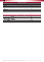
Standard delivery package

Designation

Quantity, pc

Central unit

1

RFID Tag

2

A set of wiring harness

1

Siren

1

CD

1

Reminder card

1

User manual

1

Warranty certificate

1

Connection diagram

1

Unit package

1


Specifications and operating conditions

Parameter

Value

Power supply voltage, V

9 … 15

Maximum current draw in standby mode, mA

10

Maximum current draw in operating mode, A

1.5

Operating temperature, °C

– 40 … + 85

Storage temperature, °C

– 40 … + 85

Maximum relative air humidity, %

95

Содержание Prizrak-810

Страница 1: ...T ECH NIC A L M A NUA L For modern day vehicles and drivers Car Alarm System Comfort and innovation no remote controls ...

Страница 2: ...his feature please see Integrator files for details Guard mode active state of the PINTODrive and AntiHiJack if one of these functions has entered guard mode to leave it it is required to enter PIN code otherwise engine will be locked Comfort feature feature allowing not only to lock doors from the factory remote but also to raise windows sunroof also can be closed Table of Contents Description of...

Страница 3: ...obile phone for example arm and disarm the Alarm schedule tasks start the heater etc Options of the phone control include the smart voice menu Russian and English languages are avaliable please contact your shop to change the language of the system or application TEC you may download it from application store on your device and text messaging Getting started To start using the phone application yo...

Страница 4: ...k sensor warning x7 Triggering of the tilt displacement sensor x8 Triggering of an extra sensor alarm x9 Triggering of an extra sensor warning Detailed information about events can be found in the trigger log which can be accessed from the voice menu Arming with sensor deactivation There are situations when you need to arm the Alarm with sensor input deactivation To deactivate sensors Arm the alar...

Страница 5: ...p by entering the PIN code The Guard mode phases are as follows Idle phase Warning phase Locking phase Idle phase In this phase AntiHiJack follows two different algorithms depending on the availability of Speed control If the Speed control is available AntiHiJack waits until the vehicle covers a set distance from the moment of Guard mode activation Upon that AntiHiJack goes into the Warning phase ...

Страница 6: ...or more circuits are still active i e there is no RFID tag or PIN code is not entered the vehicle will not move Authentication method can be selected when installing the Alarm without using the PUK code As a result the PUK code remains secret Authentication method can be changed without using the PUK code if The vehicle did not travel more than 10 km after the Alarm was installed the Speed control...

Страница 7: ...he RFID tag or lost forgot the PIN code You want to change identity verification method After PUK code is entered all security functions of the Alarm will be deactivated regardless the selected authentication method PUK code can be found under the scratch layer on the plastic card The factory set PIN code is 2 it is entered by using the Programming button please check the Integrator PUK code entry...

Страница 8: ...a GPS GLONASS 270 unit To locate the vehicle you need to send a text message command or via voice menu or using your mobile application Automatic window roll up The system can be programmed so that the vehicle windows are rolled up when engaging the lock Setting the electromechanical hood lock You can install an additional hood lock and program the Alarm to lock the hood when locking the vehicle a...

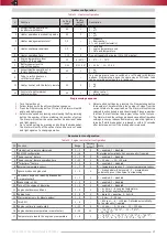
Страница 9: ...e outputs demand Useful current of output 9 depends on demand connected to negative outputs Outputs 6 15 and 17 are protected from short circuit inductive eruptions overheating and overload Connector Color Type Note Current mA 18 pin 1 Black Ground For TEC 810 830 Power for additional devices For TEC 810 830 with thermal sensor Ground for engine temperature sensor 2 Blue Yellow Heater WBUS Webasto...

Страница 10: ...iles Pins 4 13 CAN L CAN H vehicle data buses Connected to the vehicle CAN bus please see the Integrator files Pin 5 Brake lights state Used if the vehicle CAN bus does not contain brake pedal position data please see the Integrator files In such cases Pin 5 is connected to the output of brake pedal terminal switch Pin 6 Engine lock Connected to one of the relay coil contacts which is used to lock...

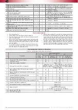
Страница 11: ...ve Set the Alarm to operate with digital buttons Menu 1 Option 4 note that this menu option can be modified only by using a built in button and before the PIN code was entered for the first time via using analog or digital buttons Any further modifications will possible only after system reset Assign activated button as the Programming button turn the ignition on push the button and hold it for at...

Страница 12: ...e of external buttons 1 2 1 analogue buttons 2 digital buttons Inputs 7 and 16 connector Х1 18 pin 5 Control of the factory security system 1 2 On 1 on 2 off 6 Sequential door opening 1 2 Off 1 on 2 off 7 Hazard lights control algorithm 1 5 1 pulse negative 2 status negative 3 pulse positive 4 status positive 5 lights control negative 8 Central lock alternative control algorithm 1 3 1 single wire ...

Страница 13: ...r to Activation by reverse gear However when parking sensors are disabled by using a control button they will not be activated when gearbox is in R position up to the next ignition or command from a control button Table 8 Configuration of programmable configuration of inputs outputs Connector Function Setting range Factory default settings 1 X1 18 pin output 15 18 pin port 1 41 Alternate hazard li...

Страница 14: ... Movement speed Emitting a pulse with a pulse frequency in proportion with the vehicle s speed 1 pulse per second corresponds to 1 km h The signal helps to evaluate the speed rather than give an exact value 20 Brake Emitting a constant level signal when the brake pedal is pressed 21 Hand brake Emitting a constant level signal when the vehicle is on hand brake 22 External lights Emitting a constant...

Страница 15: ...y in Security mode When a command to open the trunk is detected the Alarm ignores external sensor inputs and trunk terminal switch for 5 seconds until the actual opening of the trunk In 5 seconds after the trunk lid has been closed sensor inputs and the trunk will be secured 8 Parking system button The function controls parking sensors by using accessory button this may be required if there are no...

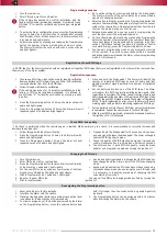
Страница 16: ... status by series of 15 signals Release the brake pedal and the Alarm goes back to displaying the menu option number If you do not press the brake pedal and abort programming of this option the Alarm will save previous settings 10 Programming algorithm for assigning a parking control button With the brake pedal pressed go to option 14 Menu 1 The Alarm will start emitting irregular audio and light ...

Страница 17: ... the Programming button the number of times matching the number of steps from the current status to the required one The Alarm will confirm the selected function by audio and visual signals Please remember that from the last function the program will go to the first one 7 The Alarm will exit the settings mode and save all configuration settings in energy independent memory when the ignition is tur...

Страница 18: ...he option status by a series of audio and light signals of a changing duration 6 Adjust option settings by pressing the Programming button the number of times matching the number of steps from the current status to the required one The Alarm will confirm the selected function by audio and visual signals Please remember that from the last function the program will go to the first one 7 The Alarm wi...

Страница 19: ...umber of signals per series is a number of registered RFID tags 6 Put the battery back into one of the RFID tags The Alarm will register this RFID tag while emitting audio signal After registration is complete the Alarm will emit series of audio and light signals indicating a number of all registered RFID tags Make sure that the number of signals equals the number of registered RFIDs If while regi...

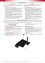
Страница 20: ...o and light signals because the current factory set option setting 1 100 meters 6 Change option 3 to do so press brogramming button 2 times i e increase setting by 2 1 2 3 The Alarm will inform you about chosen menu setting with by a series of 3 audio and light signals 300 meters 7 Exit programming mode by turning the ignition off Reset to the factory default settings The Alarm has a procedure of ...

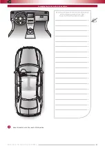
Страница 21: ... 23 Technical Manualе PRIZRAK Use the picture to draw arrangement of the Alarm units This can help to find the alarm units Arranging the Alarm units in the vehicle Keep this sketch out of the reach of third parties ...

Страница 22: ...D 1 Reminder card 1 User manual 1 Warranty certificate 1 Connection diagram 1 Unit package 1 Specifications and operating conditions Parameter Value Power supply voltage V 9 15 Maximum current draw in standby mode mA 10 Maximum current draw in operating mode A 1 5 Operating temperature C 40 85 Storage temperature C 40 85 Maximum relative air humidity 95 ...

Страница 23: ...Comfort of modern technology Endorse if you like it ...

Отзывы: