


INSTRUCTION MANUAL
GXE600 Series
TDKLambda
<Page>
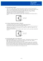
• Remote ON/OFF control
Connect a following circuit between "CNT1" terminal (Pin No.13) and "CNT2" terminal (Pin No.15) for
remote ON/OFF control. (ON/OFF control lines shall be twisted.)
•
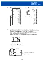
Parallel operation
Connecting PC to PC terminal
(Pin No.7)
and COM to COM terminal
(Pin No.10) of each power supply
,
the current balance function activates and output current of each power supply is equivalently supplied
to load. Wires to PC terminals, COM terminals shall be as short as possible and same length with
twist.
9/28
Load
Load


