


INSTRUCTION MANUAL
GXE600 Series
TDKLambda
<Page>
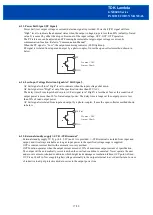
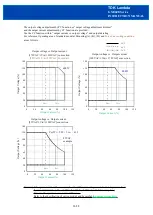
69. Parallel Operation
Current balancing function is provided. Both operation modes (A) and (B) are possible.
(A) To increase the output current
Connecting PC to PC terminal and COM to COM terminal, the current balancing function activates and
output current of each power supply is equivalently supplied to load. Wire to PC terminal, COM terminals
shall be as short as possible and same length with twist.
1. Adjust the output voltage of each power supply to be same value within 1%.
2. Use same length and type of wires for all load lines.
3. Parallel operation is possible up to 5 units.
Maximum value of output current in parallel is up to 90% of all paralleled models.
Output current of each power supply must be within output derating.
4.There is a possibility that output voltage dips at dynamic load change.
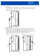
(B) To Use as a Backup Power Supply (by connecting reverse preventive diode or module
“
RP6020
”
.)
1. Adjust the output voltage higher by the value of forward voltage drop (VF) of the diode.
2. Adjust each power supply output voltage to be same.
3. Output voltage and output power should be used within specifications.
4.Use blocking diode to prevent reverse current. Diode current rating must be more than output load current.
(A)
(B)
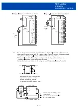
610. Remote Sensing (+S, S terminal)
Remote Sensing function is provided.
This function compensates voltage drop of wiring from output terminals to load terminals. Connect "+S" terminal
to "+" terminal of load and "S" terminal to "" terminal of load with sensing wires.
The total line voltage drop (+ side line and side line) shall be less than 0.3V.
In case that sensing line is too long, it is recommended to connect electrolytic capacitor in the following locations:
1) Across the load terminal,
2) Between "+S" terminal and "+Vm" terminal,
3) Between "S" terminal and "Vm" terminal.
Connect "+S" terminal to "+Vm" terminal, "S" terminal to "Vm" terminal with short pieces when remote
sensing function is not used. If disconnected, OVP function might trigger and voltage will be shut down.
15/28
+
Load
-
Power
Supply
+S
+Vm
Vm
S
+
V
-
V
+
V
-
V
Power
Supply
Io
Vo+Vf
Vo+Vf
+S
+Vm
Vm
S
Vo
+
Load
-
Power
Supply
PC
+
V
-
V
PC
+
V
-
V
Power
Supply
+S
+Vm
Vm
S
+S
+Vm
Vm
S
COM
COM
Power
Supply
+S
+Vm
Vm
S
+
-
Load
+
+
+
+V
V


