


INSTRUCTION MANUAL
GXE600 Series
TDKLambda
<Page>
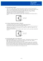
616. Remote ON/OFF Control
Remote ON/OFF control function is provided. Output ON/OFF is allowed to control without input voltage
ON/OFF, dependent on the condition of CN84 (CNT1, CNT2 and TOG terminal).
Remote ON/OFF control circuit is isolated from input and output.
CNT1, CNT2 and TOG are not connected at time of shipment, so power supply output condition is ON.
617. Sleep Mode
Sleep mode is provided and it contributes to reduction of standby power when all of the following
conditions are satisfied.
・
Output condition is
“
OFF
”
by remote ON/OFF control terminal.
・
Output condition is
“
OFF
”
by communication function when CNT mode is
“
digital CNT
”
.
・
PF signal is
“
High
”
.
・
Protection has not occurred
(
all of the alarm history indicator register are
“
0
”
).
・
The query has not been sent for more than 30 minutes.
In sleep mode, the power supply returns to normal operation by turning remote ON/OFF control to
“
ON
”
or triggering the signal of RS485. Take note that the communication function cannot be used during sleep
mode and power supply cannot receive the signal of RS485. In this case, send the query again.
When a voltage is applied to the output terminal of the power supply from the outside in sleep mode, if the
PF threshold is exceeded, PF signal keeps
“
High
”
. Refer to
“
Communication Manual
”
for details.
18/28
Third_Vcc_5V
CNT1
CNT2
TOG
Rex
Vex
Iex
SW
Third_Vcc_5V
CNT1
CNT2
TOG
SW
Third_Vcc_5V
CNT1
CNT2
TOG
SW
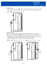
(1) Input external Voltage_Active
Connect the external resistor (Rex)
Decide Vex and Rex so that Iex is 2
~
5mA.
Decide Rex by following formula.
Rex = ( Vex 1.1 ) / ( Iex )
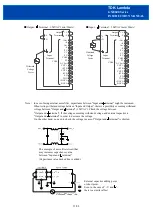
(2) OFF_Active
(3) ON_Active
ON
ON
ON
OFF
SW
Output condition
OFF
OFF
4.5
~
25.5VDC
680 12k Ω
SW
Output condition
OFF
ON
Vex
Rex
SW
Output condition
OFF
ON
ON
OFF


