

83-530-000 Rev. G
71
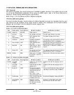
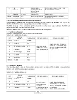
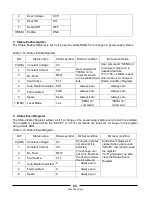
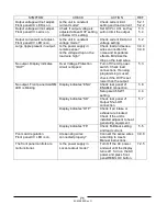
SYMPTOM
CHECK
ACTION
REF
Output voltage will not adjust.
Front panel CC LED is on.
Is the unit in constant
current mode?
Check current limit
setting and load current.
5.2.1
5.2.2
Output voltage will not adjust
Front panel CV Led is on.
Check if output voltage is
adjusted above OVP setting
or below UVL setting.
Set OVP or UVL so they
will not limit the output.
5.3
5.4
Output current will not adjust.
Front panel CV LED is on.
Is the unit in constant
voltage mode?
Check current limit and
voltage setting
5.2
Large ripple present in output.
Is the power supply in
remote sense?
Is the voltage drop on the
load wire high?
Check load and sense
wires connection for
noise and impedance
effects. Minimize the
drop on the load wires.
3.9.4
3.9.8
No output. Display indicates
“OUP”
Over Voltage Protection
circuit is tripped.
Turn off the AC power
switch. Check load
connections. If analog
programming is used,
check if the OVP is set
lower than the output.
5.3
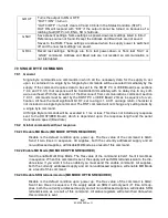
No output. Front panel ALARM
LED is blinking.
Check rear panel J1
ENABLE connection.
5.8
Display indicates “ENA”
Setup switch SW1
setting.
4.4
Display indicates “SO”
Check rear panel J1
Output Shut-Off
connection.
5.7
Display indicates “OTP”
Check if air intake or
exhaust are blocked.
Check if the unit is
installed adjacent to heat
generating equipment.
Display indicates “Fb”
Check Foldback setting
and load current.
5.5
Poor Load regulation.
Front panel CV LED is on.
Are sensing wires
connected properly?
Connect the sense wires
according to User’s
Manual instructions.
3.9.8
The front panel controls are
nonfunctional.
Is the power supply in
Local-Lockout mode?
Turn Off the AC power
and wait until the display
turns off. Turn on the AC
power and press front
panel REM/LOC button.
7.2.5
Содержание GENESYS 10KW
Страница 2: ......
Страница 3: ......
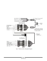
Страница 31: ...83 530 000 Rev G 28 Fig 4 2 Rear panel connections and controls...


