TDI T
URBO
T
WIN
FROM
TECH DEVELOPMENT
Publication
T1-321
Page
3
Issued November 15, 2013
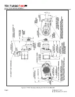
The starter should be installed with the inlet valve in a
position between horizontal and straight down. Any
condensation will be restricted to the air lines and not in
the starter.
WARNING
Do not operate this starter unless it is properly
connected to an engine.
Only qualified personnel with the corresponding
professional training may perform pneumatic and
electrical connections to the
T
URBO
T
WIN
starter.
3.1 SUPPLY LINE INSTALLATION
WARNING
Be sure to either bleed the pressurized air reservoir
and/or safety the system such as closing all valves
prior to installing any starter supply line.
T100-V
starters come standard with a flange envelope
and hole pattern accepting SAE code 61 hydraulic flange
for the inlet connection port
.
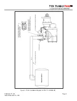
The supply line consists of
the line from the air source, a pressure regulator (when
necessary), an integral relay valve P/N: RLVA-60083-
003 with code 61 bolt pattern. A section of flexible tubing
should be installed at the starter to prevent leaks due to
engine vibration.
Care must be taken to ensure that all inlet supply line
piping is no less than 1.5” and that all components used
are capable of passing the required air flow.
NOTE
Valves with a Cv of 40 or higher is recommended.
If the supply line must be longer than 20 feet, the inlet
supply line piping should be increased to 2" in diameter
to ensure proper performance by your
T
URBO
T
WIN
.
Because turbine starters such as the
T100-V
are
sensitive to flow restrictions, care must be taken to use
uniform hose or tubing and fittings for connection of the
supply line. Tees, elbows and line length must be kept
to a minimum. TDI recommends that hose or flex
couplings be installed to eliminate possible leakage
caused by strain on the supply line.
Normally, an air strainer is not required. In dirty
environments, use of a #40 mesh Y-strainer is
recommended. The
T100-V
is highly tolerant of dirt in
the air line, however, starter life can be increased with
the use of an air strainer P/N: 52-93550-200.
A pressure regulator is required when the air supply
pressure is great enough to exceed the starter operating
pressure (at the inlet port).
The supply line should be dry-fitted for proper
alignment/location prior to final assembly. All pipe-
threaded joints should be sealed with Loctite Pipe
Thread Sealant (TDI P/N 9-94085) or equivalent for leak
tight joints prior to final assembly. Be sure to tighten all
joints to proper torque after final assembly.
CAUTION
In cold weather climates, care should be taken while
designing your installation to prevent condensation
from developing in the starter system. In systems
with a regulator or relay valve, there is the possibility
of freeze-ups.
CAUTION
On new installations, it is strongly recommended to
blow out the supply line with air to remove possible
dirt and welding slag prior to final connection to the
T
URBO
T
WIN
starter. Be sure to secure the free end
of the supply line prior to blowing out the line.
3.2 INLET PRESSURE PORT
A 1/4" NPT port is located on the air inlet. This port may
be used to check the supply pressure at the starter when
the starter is operating. Remove the 1/4" NPT pipe plug
and save for later use. Install 1/4" minimum size tubing
to the port. Route the tubing away from the starter to a
safe location away from the engine. Install a pressure
gauge on the tubing. This pressure monitoring
line/gauge may be permanently installed. Use Loctite
Pipe Thread Sealant or equivalent. Alternately, a
pressure transducer may be installed at the pressure
check port and electrical lines routed to a digital display
at the operator's station.
This pressure port is invaluable in diagnosing air starter
and/or installation problems.
3.3 EXHAUST PIPING
The turbine exhaust may be plumbed away from the
starter area.
The performance of a turbine starter will be decreased
because of back pressure when smaller than

