


TDI T
URBO
T
WIN
FROM
TECH DEVELOPMENT
Page 4
Publication T1-321
Issued November 15, 2013
recommended exhaust piping is installed. Consult your
TDI distributor for advice.
Exhaust piping should be routed downward to help
prevent any accumulation of condensation in the starter
motor.
If the overhung section of the starter is not otherwise
supported, TDI recommends that the exhaust piping be
supported with a suitable bracket(s).
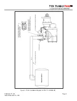
3.4 SOFT START VALVE & FILTER FITTING
The
“soft start” fitting
, by providing a slower opening
of the starter relay valve, eliminates excessive starter
pinion gear loading. The soft start fitting is identified by
P/N: 2-28243
found on its body. This fitting
MUST
be
installed at the starter relay valve as shown in figure 4. It
is screwed into the applied pressure (“IN” or “APP”) port
on the starter relay valve. There are currently no
approved substitutions for this fitting.
The
filter fitting
provides contamination protection to
the starter’s pre-engagement mechanism and the soft
start fitting installed downstream. The filter fitting is to be
installed on the “IN” port of the starter as shown in figure
4. It appears similar to the soft start fitting, however,
P/N: 2-28270
is found on its body.
CAUTION
For maximum pinion life and full warranty coverage,
the soft start valve (P/N: 2-28243) MUST be installed
in the applied pressure port (APP) of the relay valve.
WARNING
All pipes, fittings, flexible hose assemblies and
electrical harnesses are not to be used as a handle.
The starter is not to be used as a foot step.
Damage to pneumatic circuitry and/or starter can occur if
this warning is not heeded.
3.5 PIPING SYSTEM
Only type approved metallic hose assemblies are
approved in permanently pressurized compressed air
lines of starters. Non-metallic hose assemblies are
allowed only in case the piping system will be emptied
after the starting procedure.
Pipe unions must be type approved by GL. Downstream
of the pressure regulator a pressure relief valve should
be provided.
4.0 STARTER OPERATION
Prior to operation, check that all connections are tight
and free from leaks. Check the 1/4" NPT pipe plug or a
pressure gauge/transducer that may be connected to the
pressure port on the starter inlet.
WARNING
Do not operate the TDI
T
URBO
T
WIN
starter with air
pressure greater than the pressure rating on the
nameplate. This pressure is measured at the starter
inlet while the starter is running. The
T
URBO
T
WIN
starter
may only be operated in fully installed
condition.
The maximum operating pressure limit is the inlet
pressure measured at the starter’s inlet pressure check
port. To check the pressure, a 1/4"NPT pipe tap
connection is provided in the inlet housing to attach a
pressure gauge.
The static non-flowing supply pressure will always be
higher than the operating (dynamic) pressure. The
maximum pressure limit (proof pressure) that the
T100-V
starter housings may be subjected to is 600 PSIG (42
BAR). System pressure that exceeds the maximum
operating limit must use a pressure reducing device to
ensure that the operating pressure limit to the
T100-V
starter is maintained.
System static pressure that exceeds the 600 PSIG (42
BAR) limit must, in addition to pressure reducer devices,
incorporate a pressure relief valve set below 600 PSIG
(42 BAR) in the supply air line downstream of the
pressure regulator.
NOTE
For maximum life of the starter pinion and for the
protection of the engine ring gear, limit the operating
pressure to that necessary to start the engine at its most
difficult starting conditions.
All appropriate local pressure codes and pressure
limitations on other system components must be
adhered to and supersede the guidelines given in this
manual.
CAUTION
The operation of the starter may result in noise levels
exceeding 90 dBA. Protective hearing equipment
must be worn at all times.


