Test and Alignment Specification for MT5331 Series (v0 91)
Page 21 of 26
Go to “
Factory menu
Other
Update CI+ Credential
Update From USB
“ and then press RCU
“
OK/
►” key
The
“Valid” flag should now be enabled (turns to “Yes”), “Custom Code” should displayed “TCL” and
“Serial Num.” field should updated with Key number.
Remove USB stick
Note: If unfortunately the process failed, you may need to download new CI key and repeat operation again.
Appendix
⑺
“
How to upgrade CI Key using MTK tool
”
Connect UART interface to suitable manufacturing TV input connector
Launch MTK tool with version above v2.48-05
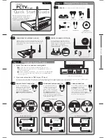
Click on “Browse” button and select "All files(*.*)" filter, then browse any “
*.key
” file like below snapshot
Modify "Custom Burning Address:" to "790000", then start to upgrade
Restart TV
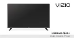
Go to
“
Factory menu
Other
Update CI+ Credential
Update CI+ Credential
”, then press
RCU ”
OK/
►” key. The “Valid” flag should now be enabled (turns to “Yes”), “Custom Code” should display
“TCL” and corresponding “Serial Number” should be updated as well like onto below snapshot:
Remove UART connection
Note: If unfortunately the process failed, you may need to download new CI key and repeat operation again.
Appendix
⑻
“How to upgrade MAC address using USB”
MAC for USB upgrade method as following
:
Create a new folder(name: _MAC) in the USB disk root directory.
Put the MAC file into the root directory of the USB disk
Inster the USB disk into TV,in the factory menu,selected other->Update MAC address->Update
From USB
Содержание MT31-AP
Страница 47: ......