1
2
DASH PANEL
Black
Blue/Black
Brown
Gray/black
Red
Blue/White
Violet/Black
White/Black
Gray/White
13
1
6
Violet/
Black
9
14
5
8
12
3
7
11
10
F
Red
Brown
Red
DASH PANEL
High/Low
Switch
2
F & R
Switch
Key Switch
Horn
Switch
Red
View from pin side
7
6
9
3
4
1
Smart View
Display
Black
Blue
A1
A2
Blue
White
Red
2
16
14
Black
MOTION
ALARM
AUTOMATIC
ELECTRIC
BRAKE
10
6
12
7
3
5
8
4
11
1
9
13
White
White
4
9
5
10
6
3
2
8
Black/White
Violet/Black
Violet/Black
1
BLACK
Black
RED
PANEL
CONTROL
A
White
Black
Red
Red
Red
Red
Red
ISO
Black
NOTE: The charger interlock may
be located in the charger cabinet.
GROUND
Green
CHARGER
MOTOR
F2
Yellow
F1
Green
AC CHARGER
CORD
CHARGER
INTERLOCK
White
GROUND
Green
Blue
Blue
2
1
Black
Gray/White
Red/White
Blue
Yellow
Green/Black
Gray/Black
White/Black
Blue/Black
Violet/Black
Red
Red
Blue/White
White
White
Violet/Black
Black
Gray/White
Red/White
Blue
Yellow
Green/Black
Gray/Black
White/Black
Blue/Black
Violet/Black
Red
Blue/White
Red/White
Blue
Yellow
Green/Black
Gray/Black
White/Black
Blue/Black
Violet/Black
Red
Blue/White
Gray/White
Blue/Black
White/Black
Violet/Black
Gray/black
Green/Black
BATTERY POSITIVE
BATTERY NEGATIVE
Red
Black
Red
Red
Black
Black
NOTE: Charger wire
routing may vary
B 2-38 RR Special, Sevcon control system, no 12 volt tap.
Diagram inculdes options that may not be installed on your vehicle
Red/Black
Black
Green/Black
Yellow
Black
Violet/Black
Throttle Module
FS-3
5
1
9
FS-1
8
4
0-5 Volt output
B+ Input
B- Input
Green/Black
Brown(31)
Black
Can-Buss Connector
The Smart View
Display is wired
through a cable to
the Can-Buss
connector on the
speed control
Front
Front/left
Front/Right
Rear/Right
Rear/Left
HORN
Blue/White
White
Brake
Switch
Front Light
Front/left
Front/Right
Rear/Right
Rear/Left
Red
Brown(32)
Brown(33)
Brown(43)
Brown(42)
Brown
Red
Red
Brown
Brown
Brown
Brown
Brown
White
White
White
White
White
White
White
White
White
White
White
White
White
White
Gray/White
Backup Light
Red
Gray
Gray
Gray
Brown
White
White
Tail Lights
Black
Содержание MB-238-00
Страница 2: ......
Страница 6: ...TAYLOR DUNN...
Страница 12: ...B2 48 With Stake Side Dump Bed Option SC1 00 Stock Chaser E4 55 Sit Down Tow Tractor C4 25 Sit Down Tow Tractor...
Страница 28: ...TAYLOR DUNN...
Страница 44: ...Maintenance Service and Repair Steering Page 8 Exploded View of Steering Gear...
Страница 64: ...TAYLOR DUNN...
Страница 94: ...Maintenance Service and Repair Transmission Page 20 NOTE Values shown are for reference only C D...
Страница 112: ...TAYLOR DUNN...
Страница 149: ...TABLE OF CONTENTS Wire Diagrams Complete Vehicle 2...
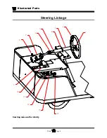
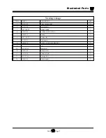
Страница 154: ...Illustrated Parts Parts Page 4 Steering Linkage 2 1 3 4 6 7 8 9 10 11 12 13 14 5 Cowling removed for clarity...
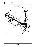
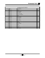
Страница 156: ...Illustrated Parts Parts Page 6 Steering Gear 4 1 6 8 7 5 9 10 2 3 14 17 12 11 13 15 16 Exploded Steering Gear dwg...
Страница 158: ...Illustrated Parts Parts Page 8 Transmission Gear Case...
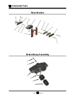
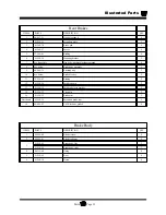
Страница 162: ...Illustrated Parts Parts Page 12 Rear Brakes Brake Body Assembly...
Страница 166: ...Illustrated Parts Parts Page 16 Brake Lines Illustration not available...
Страница 168: ...Illustrated Parts Parts Page 18 Motor...
Страница 170: ...Illustrated Parts Parts Page 20 Wheels and Tires Ref wheel hub 1 2 3 Rear Suspension...
Страница 172: ...Illustrated Parts Parts Page 22 Speed Control Panel Instrument Panel dash...
Страница 174: ...Illustrated Parts Parts Page 24 Miscellaneous Electrical Miscellaneous Wire Harness Clamps 2 3 17 16 15 18 4...
Страница 182: ...Illustrated Parts Parts Page 32 Seat Cushions Deck and Lights Frame Illustration not available...
Страница 184: ...Illustrated Parts Parts Page 34 Decals...
Страница 186: ...Illustrated Parts Parts Page 36 Hitches...

