Maintenance, Service, and Repair
Steering
Page 2
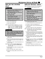
Center the Steering Wheel
1. Inspect the steering alignment and adjust as
required. Refer to Front End Alignment for
information regarding aligning the steering.
2. Drive the vehicle in a straight line and stop.
8. Tie off the front fork so that it cannot turn.
9. Remove and reinstall the steering wheel orientated
as shown in the illustration with one spoke pointing
straight up. Tighten the
steering wheel nut to
50-60 ft-lbs.
10. Untie the front fork.
11. Reconnect the main
positive and negative
cables at the batteries.
12. Remove the blocks
from behind the wheels.
13. Release the parking brake and test drive the
vehicle.
FRONT END ALIGNMENT
6. Center the steering gear.
7. Tie off the steering wheel so that it cannot rotate.
8. Adjust both steering stops to their shortest lengths.
NOTE: The front steering stop is for right turns, the
rear steering stop is for left turns.
9. Inspect the position of the pitman arm. It should
be close to centered between the two steering
stops. If the pitman arm is significantly off center,
then remove and reinstall the pitman arm so that
it is centered. Torque the pitman arm nut to 75-
100 ft-lbs.
10. Untie the steering wheel.
11. Reconnect the batteries and remove the blocks
from the wheels.
12. Drive the vehicle in a right turn until the turning
radius is at 155-inches. Stop and adjust the right
turn steering stop until it touches the pitman arm.
Do not drive the vehicle while the steering
wheel or front fork is tied in position.
Driving the vehicle while the steering
wheel or front fork tied in position may
cause loss of control of the vehicle resulting
in severe bodily injury and/or property
damage.
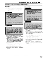
1. Make sure the key-switch is in the “OFF”
position, then remove the key.
2. Place the forward-reverse switch in the
center “OFF” position.
3. Set the park brake.
4. Place blocks under the rear wheels to
prevent vehicle movement.
5. Disconnect the main positive and
negative cables at the batteries.
Disconnect the batteries, set the park brake
and block the wheels before making any
adjustments.
13. Repeat the previous step for a left turn.
14. Tighten all jam nuts.
15. Check the turning radius in both the left and right
turn. Repeat this procedure if not within
specifications.
Do not drive the vehicle while the steering
wheel or front fork is tied in position.
Driving the vehicle while the steering
wheel or front fork tied in position may
cause loss of control of the vehicle resulting
in severe bodily injury and/or property
damage.
3. Make sure the key-switch is in the “OFF”
position, then remove the key.
4. Place the forward-reverse switch in the
center “OFF” position.
5. Set the park brake.
6. Place blocks under the rear wheels to
prevent vehicle movement.
7. Disconnect the main positive and
negative cables at the batteries.
Содержание MB-238-00
Страница 2: ......
Страница 6: ...TAYLOR DUNN...
Страница 12: ...B2 48 With Stake Side Dump Bed Option SC1 00 Stock Chaser E4 55 Sit Down Tow Tractor C4 25 Sit Down Tow Tractor...
Страница 28: ...TAYLOR DUNN...
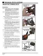
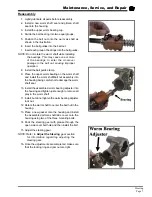
Страница 44: ...Maintenance Service and Repair Steering Page 8 Exploded View of Steering Gear...
Страница 64: ...TAYLOR DUNN...
Страница 94: ...Maintenance Service and Repair Transmission Page 20 NOTE Values shown are for reference only C D...
Страница 112: ...TAYLOR DUNN...
Страница 149: ...TABLE OF CONTENTS Wire Diagrams Complete Vehicle 2...
Страница 154: ...Illustrated Parts Parts Page 4 Steering Linkage 2 1 3 4 6 7 8 9 10 11 12 13 14 5 Cowling removed for clarity...
Страница 156: ...Illustrated Parts Parts Page 6 Steering Gear 4 1 6 8 7 5 9 10 2 3 14 17 12 11 13 15 16 Exploded Steering Gear dwg...
Страница 158: ...Illustrated Parts Parts Page 8 Transmission Gear Case...
Страница 162: ...Illustrated Parts Parts Page 12 Rear Brakes Brake Body Assembly...
Страница 166: ...Illustrated Parts Parts Page 16 Brake Lines Illustration not available...
Страница 168: ...Illustrated Parts Parts Page 18 Motor...
Страница 170: ...Illustrated Parts Parts Page 20 Wheels and Tires Ref wheel hub 1 2 3 Rear Suspension...
Страница 172: ...Illustrated Parts Parts Page 22 Speed Control Panel Instrument Panel dash...
Страница 174: ...Illustrated Parts Parts Page 24 Miscellaneous Electrical Miscellaneous Wire Harness Clamps 2 3 17 16 15 18 4...
Страница 182: ...Illustrated Parts Parts Page 32 Seat Cushions Deck and Lights Frame Illustration not available...
Страница 184: ...Illustrated Parts Parts Page 34 Decals...
Страница 186: ...Illustrated Parts Parts Page 36 Hitches...

