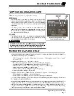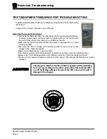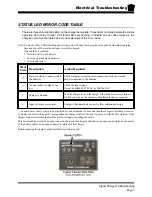
Electrical Troubleshooting
Troubleshooting
Page 6
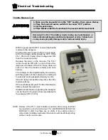
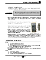
Throttle Module Test
With the power switch OFF, connect the throttle
module to the analyzer.
Position the power switch to the 0-5 volt range.
All but the power lamp should be OFF. If the
FS-1, FS-3 or OV lamp (Over Voltage) are ON,
then the module is faulty.
Depress the lever on the module. The FS-1
lamp should be ON with no more that a few
degrees of rotation. If the FS-1 lamp does not
come on, then the module is faulty (see note
below).
The voltage on the digital display should vary
with the position of the module arm, starting at
0-volts and ending at approximately 5-volts.
If the OV lamp comes ON at any time, then the
module is faulty.
If the Low battery lamp is ON, then the analyzer
battery should be replaced.
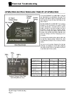
Additional information regarding the analyzer
can be found in the instructions provided with
the analyzer (D0-110-53)
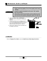
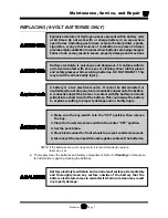
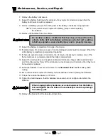
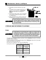
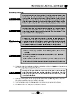
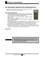
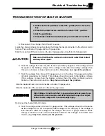
Disconnect both of the battery leads during any maintenance or
before disconnecting any electrical component or wire. Failure to do
so may cause property damage and/or serious bodily injury.
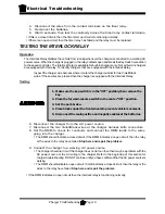
1. Make sure the key-switch is in the “OFF” position, then remove the key.
2. Place the forward-reverse switch in the center “OFF” position.
3. Set the park brake.
4. Place blocks under the front wheels to prevent vehicle movement.
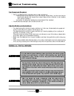
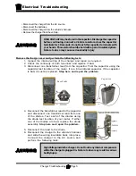
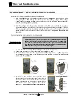
NOTE: Failures of the FS-1 circuit indicate a possible vehicle wiring fault that
has resulted in a short circuit across FS-1. BEFORE REPLACING THE
MODULE: Confirm that there are no shorts in the vehicle wiring or
components. Installing a replacement module in a vehicle with faulty wiring
will burn out the new module.
Содержание B0-248-48AC
Страница 2: ......
Страница 14: ...B2 48 With Stake Side Dump Bed Option SC1 00 Stock Chaser E4 55 Sit Down Tow Tractor C4 25 Sit Down Tow Tractor...
Страница 33: ...TABLE OF CONTENTS General Maintenance Maintenance Guidelines 2 Troubleshooting Guide 3 Lubrication Chart 4...
Страница 70: ...Maintenance Service and Repair Steering Page 22 Exploded View of Steering Gear...
Страница 88: ...TAYLOR DUNN...
Страница 108: ...Maintenance Service and Repair Transmission Page 20 NOTE Values shown are for reference only C D...
Страница 114: ...TAYLOR DUNN...
Страница 120: ...TAYLOR DUNN...
Страница 132: ...TAYLOR DUNN...
Страница 134: ...TAYLOR DUNN...
Страница 164: ...Illustrated Parts Parts Page 2 Front Axle...
Страница 166: ...Illustrated Parts Parts Page 4 Steering Knuckle...
Страница 168: ...Illustrated Parts Parts Page 6 Steering Linkage...
Страница 174: ...Illustrated Parts Parts Page 12 Rear Suspension View from rear...
Страница 176: ...Illustrated Parts Parts Page 14 Transmission Gear Case...
Страница 180: ...Illustrated Parts Parts Page 18 Rear Brakes Front Brakes...
Страница 182: ...Illustrated Parts Parts Page 20 Brake Lines Master Cylinder...
Страница 184: ...Illustrated Parts Parts Page 22 Motor...
Страница 186: ...Illustrated Parts Parts Page 24 Motor Mount Apply 94 421 34 grease to inside of motor coupler...
Страница 188: ...Illustrated Parts Parts Page 26 Wheels and Tires Ref wheel hub 1 2 5 assembly 4 3 6 7 8 9 10...
Страница 190: ...Illustrated Parts Parts Page 28 Instrument Panel Up To Serial 179501 Instrument Panel Starting Serial 179502...
Страница 196: ...Illustrated Parts Parts Page 34 Lighting Stobe Light 4 1 2 3 5 6 7...
Страница 206: ...Illustrated Parts Parts Page 44 Seat Cushions and Deck...
Страница 208: ...Illustrated Parts Parts Page 46 Mirrors 92 202 00 Assembly Miscellaneous Frame Components...
Страница 210: ...Illustrated Parts Parts Page 48 Decals...
Страница 212: ...Illustrated Parts Parts Page 50 Cab Options Steel Cab Fiberglass cab...
Страница 216: ...Illustrated Parts Parts Page 54 3 8 9 6 7 5 4 2 1 Typical door assembly Door Options Fiberglass Cab...
Страница 218: ...Illustrated Parts Parts Page 56 Hydraulic Dump Body Option...
Страница 220: ...Illustrated Parts Parts Page 58 Rear Cargo Box 1 2 3 4 5 6 5 Top Covers...
Страница 222: ...Illustrated Parts Parts Page 60 Hitches...
Страница 224: ...TAYLOR DUNN...

