Maintenance, Service, and Repair
Transmission
Page 16
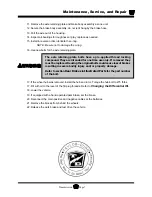
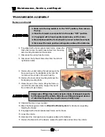
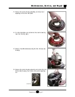
10. Mark the position of each carrier bearing ring nut in relation to the
drive housing and cover and then remove the differential
assembly, do not allow the ring nuts to rotate.
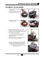
11. Install the pinion gear. Re-shim if required.
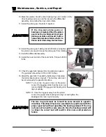
12. Install the pinion gear holding tool (96-500-42) and tighten
the pinion nut enough to keep the pinion gear from rotating.
13. Install the differential assembly.
14. Install the cover and all of the cover bolts. Torque to 45-50
ft-lbs.
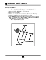
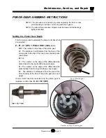
If the ring and pinion gears or
bearings are replaced then the pinion
gear must be re-shimmed. Improper
pinion gear shims will result in drive
noise and premature failure. Refer to
Pinion Gear Shimming Instructions.
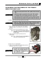
15. Check the gear lash between the ring and pinion gears.
The gear lash should be 0.005 to 0.007 inches.
16. Adjust the gear lash if needed by tightening or loosening
the carrier bearing race ring nuts. The two ring nuts must
be turned equally in opposite directions.
NOTE: To move the ring gear closer to the pinion:
Loosen the housing carrier bearing race ring
nuts and tighten the cover carrier bearing race
ring nut equally.
NOTE: To move the ring gear away from the pinion:
Loosen the cover carrier bearing race ring nut and tighten the
housing carrier race ring nut equally.
The two ring nuts must be turned the same amount in opposite
directions. This allows the carrier assembly to be positioned with the
proper gear lash without upsetting the bearing preload. If the ring
nuts are not turned the same amount, then the bearing preload will
no longer be correct and will result in drive noise and premature
failure.
Содержание B0-248-48AC
Страница 2: ......
Страница 14: ...B2 48 With Stake Side Dump Bed Option SC1 00 Stock Chaser E4 55 Sit Down Tow Tractor C4 25 Sit Down Tow Tractor...
Страница 33: ...TABLE OF CONTENTS General Maintenance Maintenance Guidelines 2 Troubleshooting Guide 3 Lubrication Chart 4...
Страница 70: ...Maintenance Service and Repair Steering Page 22 Exploded View of Steering Gear...
Страница 88: ...TAYLOR DUNN...
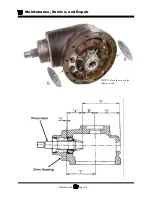
Страница 108: ...Maintenance Service and Repair Transmission Page 20 NOTE Values shown are for reference only C D...
Страница 114: ...TAYLOR DUNN...
Страница 120: ...TAYLOR DUNN...
Страница 132: ...TAYLOR DUNN...
Страница 134: ...TAYLOR DUNN...
Страница 164: ...Illustrated Parts Parts Page 2 Front Axle...
Страница 166: ...Illustrated Parts Parts Page 4 Steering Knuckle...
Страница 168: ...Illustrated Parts Parts Page 6 Steering Linkage...
Страница 174: ...Illustrated Parts Parts Page 12 Rear Suspension View from rear...
Страница 176: ...Illustrated Parts Parts Page 14 Transmission Gear Case...
Страница 180: ...Illustrated Parts Parts Page 18 Rear Brakes Front Brakes...
Страница 182: ...Illustrated Parts Parts Page 20 Brake Lines Master Cylinder...
Страница 184: ...Illustrated Parts Parts Page 22 Motor...
Страница 186: ...Illustrated Parts Parts Page 24 Motor Mount Apply 94 421 34 grease to inside of motor coupler...
Страница 188: ...Illustrated Parts Parts Page 26 Wheels and Tires Ref wheel hub 1 2 5 assembly 4 3 6 7 8 9 10...
Страница 190: ...Illustrated Parts Parts Page 28 Instrument Panel Up To Serial 179501 Instrument Panel Starting Serial 179502...
Страница 196: ...Illustrated Parts Parts Page 34 Lighting Stobe Light 4 1 2 3 5 6 7...
Страница 206: ...Illustrated Parts Parts Page 44 Seat Cushions and Deck...
Страница 208: ...Illustrated Parts Parts Page 46 Mirrors 92 202 00 Assembly Miscellaneous Frame Components...
Страница 210: ...Illustrated Parts Parts Page 48 Decals...
Страница 212: ...Illustrated Parts Parts Page 50 Cab Options Steel Cab Fiberglass cab...
Страница 216: ...Illustrated Parts Parts Page 54 3 8 9 6 7 5 4 2 1 Typical door assembly Door Options Fiberglass Cab...
Страница 218: ...Illustrated Parts Parts Page 56 Hydraulic Dump Body Option...
Страница 220: ...Illustrated Parts Parts Page 58 Rear Cargo Box 1 2 3 4 5 6 5 Top Covers...
Страница 222: ...Illustrated Parts Parts Page 60 Hitches...
Страница 224: ...TAYLOR DUNN...

