Maintenance, Service, and Repair
F2/F3 Transmission
Page 9
DIFFERENTIAL ASSEMBLY (3
RD
MEMBER)
Disassemble
NOTE: Bearings and races must be replaced as a
set. If any one bearing or race is worn, its
mate must also be replaced. It is
recommended to replace all bearings and
races in the 3rd member as a set.
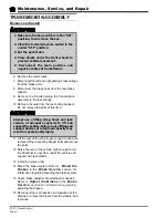
1. Drain the oil from the differential housing and chain
case. Refer to section
Change the Oil
for
information regarding draining the oil.
2. Remove the transmission assembly from the
vehicle. Refer to
Transmission Assembly:
Remove and Install
for information regarding
removing the transmission.
3. Remove both rear axle assemblies. Refer to
section
Rear Axle: Remove and Install
for
information regarding removing the axles.
4. Remove the chain case and backing plate from
the 3rd member. Refer to section
Chain Case:
Disassemble
for information regarding removing
the chain case.
5. Remove the nuts holding the 3rd member to the
axle housing and remove the 3rd member from
the housing.
6. Install a spacer on the pinion shaft so that the
pinion nut can be installed and tightened.
Measuring backlash
7. While rotating the pinion shaft, tighten the pinion
nut to 100 ft-lbs.
8. Measure and record the ring and pinion gear
backlash. This setting will be used during
reassembly.
9. Remove the pinion housing and pinion gear from
the 3rd member.
NOTE: Do not lose the spacers and shims in the
pinion housing or the pinion housing shim(s).
10. If required, remove the rear tapered bearing from
the pinion shaft and discard.
NOTE: Do not remove the bearing unless it requires
replacement. Removing the rear bearing will
damage the bearing. Replacing this bearing
will require re-shimming of the pinion shaft.
11. If required, remove the bearing races from the
pinion housing.
12. Mark the differential bearing caps and 3rd member
housing so that they can be reassembled in their
original location. Refer to illustration at end of
section.
NOTE: The caps cannot be interchanged or replaced.
If the caps are lost or damaged then the entire
3rd member assembly must be replaced.
13. Remove the differential bearing caps, bearing
adjusting nuts and races.
14. Remove the differential assembly from the 3rd
member.
15. Mark the ring gear and differential housing so that
the ring gear can be reinstalled in the same
orientation.
16. Remove the bearings from the differential housing
and discard.
NOTE: Removing the bearings will damage the
bearings. Do not remove the bearings unless
they require replacement.
17. Remove the ring gear
from the differential
housing.
18. Remove the differential
shaft locking roll pin.
19. Split the 2-piece
differential housing.
20. Drive the differential
pinion shaft out of the
housing with a brass
drift punch.
21. Remove the differential
gears, axle gears, and
thrust washers.
Содержание B0-012-10
Страница 2: ......
Страница 12: ...B2 48 With Stake Side Dump Bed Option SC1 00 Stock Chaser E4 55 Sit Down Tow Tractor C4 25 Sit Down Tow Tractor...
Страница 26: ...TAYLOR DUNN...
Страница 53: ...Maintenance Service and Repair Steering Page 15 Exploded View of Steering Gear...
Страница 54: ...TAYLOR DUNN...
Страница 69: ...TABLE OF CONTENTS Throttle Linkage Adjustments 2 Magnetic Sensor Module 2 Pot Box module 3 Throttle Linkage...
Страница 72: ...TAYLOR DUNN...
Страница 85: ...Maintenance Service and Repair F2 F3 Transmission Page 13 EXPLODED VIEW...
Страница 86: ...TAYLOR DUNN...
Страница 94: ...TAYLOR DUNN...
Страница 100: ...TAYLOR DUNN...
Страница 106: ...TAYLOR DUNN...
Страница 116: ...TAYLOR DUNN...
Страница 172: ...Illustrated Parts Parts Page 2 Front Axle...
Страница 176: ...Illustrated Parts Parts Page 6 STEERING...
Страница 178: ...Illustrated Parts Parts Page 8 STEERING GEAR...
Страница 180: ...Illustrated Parts Parts Page 10 PARK BRAKE...
Страница 182: ...Illustrated Parts Parts Page 12 DEADMAN SEAT BRAKE optional...
Страница 184: ...Illustrated Parts Parts Page 14 MASTER CYLINDER BRAKE LINKAGE...
Страница 186: ...Illustrated Parts Parts Page 16 HYDRAULIC BRAKE LINES...
Страница 188: ...Illustrated Parts Parts Page 18 FRONT BRAKES optional REAR BRAKES...
Страница 195: ...Illustrated Parts Parts Page 25 This page intentionally left blank...
Страница 196: ...Illustrated Parts Parts Page 26 Motors P1 16 17 6 8 15 Typical GE Motor 9 12 13 9 5 3 4 2 1 14 10 11 7...
Страница 198: ...Illustrated Parts Parts Page 28 16 17 6 8 15 Typical GE Motor 9 12 13 9 5 3 4 2 1 14 10 11 7 Motors P2...
Страница 202: ...Illustrated Parts Parts Page 32 POWER TRACTION DRIVE...
Страница 204: ...Illustrated Parts Parts Page 34 REAR DIFFERENTIAL...
Страница 208: ...Illustrated Parts Parts Page 38 Tires Wheels 10 Ref wheel hub 1 2 5 assembly 4 3 6 7 8 9...
Страница 210: ...Illustrated Parts Parts Page 40 CONTROL PANEL...
Страница 212: ...Illustrated Parts Parts Page 42 CONTROL PANEL EE...
Страница 216: ...Illustrated Parts Parts Page 46 DECALS MISCELLANEOUS STANDARD PARTS...
Страница 218: ...Illustrated Parts Parts Page 48 MISCELLANEOUS STANDARD PARTS Cont d...
Страница 220: ...Illustrated Parts Parts Page 50 Options...
Страница 222: ...Illustrated Parts Parts Page 52...
Страница 224: ...Illustrated Parts Parts Page 54...
Страница 226: ...Illustrated Parts Parts Page 56...
Страница 228: ...Illustrated Parts Parts Page 58...
Страница 230: ...Illustrated Parts Parts Page 60...
Страница 232: ...Illustrated Parts Parts Page 62...
Страница 234: ...Illustrated Parts Parts Page 64...
Страница 238: ...Illustrated Parts Parts Page 68...
Страница 244: ...Illustrated Parts Parts Page 74...
Страница 246: ...TAYLOR DUNN...


