


Curtis PMC Troubleshooting
Page 30
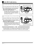
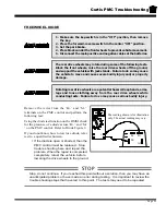
Check continuity from ‘S1’ to the frame of the
motor.
If you do not know how to test for continuity,
refer test to a qualified technician.
This should be an open circuit. If there is
continuity from ‘S1’ to the frame of the
motor, then the motor field is shorted.
Stop trouble shooting here and repair the
problem. When the repair is completed,
completely retest the vehicle before
lowering the drive wheels to the ground,
otherwise continue to Motor Inspection.
Motor Inspection
1. Remove and disassemble the motor.
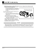
2. Visually inspect the inside of the brush end housing. If there are any silver specs of metal
around the inside of the housing, it indicates that the armature has overheated and melted
the solder around the commutator. The armature is bad and the motor must be replaced.
Stop here and repair the problem, otherwise continue with the next test.
3. Visually inspect the armature wires where they loop around at the shaft end of the armature.
The insulation should be a light to medium reddish brown color. If the insulation is dark
brown to black or the insulation is cracked and peeling, then the armature has been
overheated and burnt. The motor must be replaced. Stop here and repair the problem,
otherwise continue with the next test.
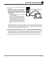
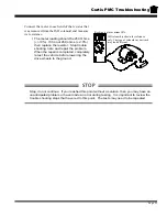
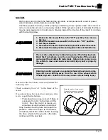
4. Perform a continuity test around the armature commutator. Place one of the test leads on
a single commutator segment. While holding the first test lead on the segment, check the
continuity to the other segments around the commutator.
If you do not know how to test for continuity,
refer test to a qualified technician.
•
There should be continuity on each
commutator segment. If an open
segment is found, the armature is bad
and the motor must be replaced. Stop
trouble shooting here and repair the
problem. When the repair is completed,
completely retest the vehicle before
lowering the drive wheels to the ground.
STOP
Stop, do not continue. If you reached this point without a solution, then you may have an
unanticipated problem or have made an error during testing. It is important to review the
trouble shooting steps that have led to this point. The tests may need to be repeated.
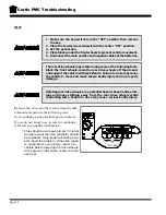
Motor shown for reference only.
Terminal positions on your motor
may not be in the same location.
A1
S2
S1
A2
_
+
Check each segment
all of the way around
the commutator
Hold this lead
in place
Commutator
_
+
Содержание B0-012-10
Страница 2: ......
Страница 12: ...B2 48 With Stake Side Dump Bed Option SC1 00 Stock Chaser E4 55 Sit Down Tow Tractor C4 25 Sit Down Tow Tractor...
Страница 26: ...TAYLOR DUNN...
Страница 53: ...Maintenance Service and Repair Steering Page 15 Exploded View of Steering Gear...
Страница 54: ...TAYLOR DUNN...
Страница 69: ...TABLE OF CONTENTS Throttle Linkage Adjustments 2 Magnetic Sensor Module 2 Pot Box module 3 Throttle Linkage...
Страница 72: ...TAYLOR DUNN...
Страница 85: ...Maintenance Service and Repair F2 F3 Transmission Page 13 EXPLODED VIEW...
Страница 86: ...TAYLOR DUNN...
Страница 94: ...TAYLOR DUNN...
Страница 100: ...TAYLOR DUNN...
Страница 106: ...TAYLOR DUNN...
Страница 116: ...TAYLOR DUNN...
Страница 172: ...Illustrated Parts Parts Page 2 Front Axle...
Страница 176: ...Illustrated Parts Parts Page 6 STEERING...
Страница 178: ...Illustrated Parts Parts Page 8 STEERING GEAR...
Страница 180: ...Illustrated Parts Parts Page 10 PARK BRAKE...
Страница 182: ...Illustrated Parts Parts Page 12 DEADMAN SEAT BRAKE optional...
Страница 184: ...Illustrated Parts Parts Page 14 MASTER CYLINDER BRAKE LINKAGE...
Страница 186: ...Illustrated Parts Parts Page 16 HYDRAULIC BRAKE LINES...
Страница 188: ...Illustrated Parts Parts Page 18 FRONT BRAKES optional REAR BRAKES...
Страница 195: ...Illustrated Parts Parts Page 25 This page intentionally left blank...
Страница 196: ...Illustrated Parts Parts Page 26 Motors P1 16 17 6 8 15 Typical GE Motor 9 12 13 9 5 3 4 2 1 14 10 11 7...
Страница 198: ...Illustrated Parts Parts Page 28 16 17 6 8 15 Typical GE Motor 9 12 13 9 5 3 4 2 1 14 10 11 7 Motors P2...
Страница 202: ...Illustrated Parts Parts Page 32 POWER TRACTION DRIVE...
Страница 204: ...Illustrated Parts Parts Page 34 REAR DIFFERENTIAL...
Страница 208: ...Illustrated Parts Parts Page 38 Tires Wheels 10 Ref wheel hub 1 2 5 assembly 4 3 6 7 8 9...
Страница 210: ...Illustrated Parts Parts Page 40 CONTROL PANEL...
Страница 212: ...Illustrated Parts Parts Page 42 CONTROL PANEL EE...
Страница 216: ...Illustrated Parts Parts Page 46 DECALS MISCELLANEOUS STANDARD PARTS...
Страница 218: ...Illustrated Parts Parts Page 48 MISCELLANEOUS STANDARD PARTS Cont d...
Страница 220: ...Illustrated Parts Parts Page 50 Options...
Страница 222: ...Illustrated Parts Parts Page 52...
Страница 224: ...Illustrated Parts Parts Page 54...
Страница 226: ...Illustrated Parts Parts Page 56...
Страница 228: ...Illustrated Parts Parts Page 58...
Страница 230: ...Illustrated Parts Parts Page 60...
Страница 232: ...Illustrated Parts Parts Page 62...
Страница 234: ...Illustrated Parts Parts Page 64...
Страница 238: ...Illustrated Parts Parts Page 68...
Страница 244: ...Illustrated Parts Parts Page 74...
Страница 246: ...TAYLOR DUNN...


