


Maintenance, Service, and Repair
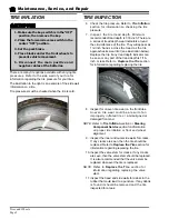
Tires and Wheels
Page 3
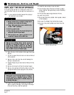
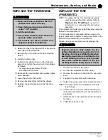
REPLACE THE TIRE/WHEEL
6. Raise the wheel to be replaced off of the ground
and support with jack stands.
7. Remove the 4 or 5 wheel nuts and remove the
wheel.
8. Install in reverse order.
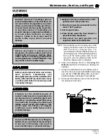
9. Following the pattern shown on the following
page, cross tighten the wheel nuts in two stages
as follows:
1st stage to approximately 20 ft-lbs.
2nd stage to 80-90 ft-lbs.
10. Reconnect the main positive and negative cables
at the batteries.
11. Lower the wheel to the ground.
12. Remove the blocks from behind the wheels.
13. Release the parking brake and test drive the
vehicle.
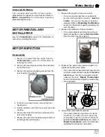
1. Make sure the key-switch is in the “OFF”
position, then remove the key.
2. Place the forward-reverse switch in the
center “OFF” position.
3. Set the park brake.
4. Place blocks under the front wheels to
prevent vehicle movement.
5. Disconnect the main positive and
negative cables at the batteries.
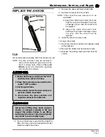
REPLACE THE TIRE
(PNEUMATIC)
NOTE; To replace the tire, the tire/wheel assembly
must be removed from the vehicle. Refer to
Replace the Tire/Wheel
section for
information on removing the tire/wheel
assembly.
Tire replacement should only be performed by personnel
trained in tire replacement.
The tire replacement procedure will be unique to the
type of replacement equipment being used. Refer to the
instructions provided with your equipment.
Always use a new valve stem when replacing a tire.
1. Remove the tire from the wheel.
2. Cut the old valve stem off of the wheel.
3. Remove the valve stem cap from the new valve
stem.
4. Lubricate the valve stem with liquid soap.
5. Install a new valve stem using a valve stem tool.
NOTE: The valve stem tool is available at most auto
repair shops.
6. Install the tire onto the wheel following the
instructions provided with your tire replacement
equipment.
7. Inflate the tire to the proper pressure and check
for leaks.
8. Install the valve stem cap.
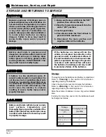
Explosion Hazard. Fully deflate the tire
before attempting to remove the tire from
the wheel. Do not over inflate the tire when
seating the bead. Failure to deflate the tire
or over inflating the tire to seat the bead
may cause explosive failure of the tire
resulting in severe bodily injury or death.
Содержание B0-012-10
Страница 2: ......
Страница 12: ...B2 48 With Stake Side Dump Bed Option SC1 00 Stock Chaser E4 55 Sit Down Tow Tractor C4 25 Sit Down Tow Tractor...
Страница 26: ...TAYLOR DUNN...
Страница 53: ...Maintenance Service and Repair Steering Page 15 Exploded View of Steering Gear...
Страница 54: ...TAYLOR DUNN...
Страница 69: ...TABLE OF CONTENTS Throttle Linkage Adjustments 2 Magnetic Sensor Module 2 Pot Box module 3 Throttle Linkage...
Страница 72: ...TAYLOR DUNN...
Страница 85: ...Maintenance Service and Repair F2 F3 Transmission Page 13 EXPLODED VIEW...
Страница 86: ...TAYLOR DUNN...
Страница 94: ...TAYLOR DUNN...
Страница 100: ...TAYLOR DUNN...
Страница 106: ...TAYLOR DUNN...
Страница 116: ...TAYLOR DUNN...
Страница 172: ...Illustrated Parts Parts Page 2 Front Axle...
Страница 176: ...Illustrated Parts Parts Page 6 STEERING...
Страница 178: ...Illustrated Parts Parts Page 8 STEERING GEAR...
Страница 180: ...Illustrated Parts Parts Page 10 PARK BRAKE...
Страница 182: ...Illustrated Parts Parts Page 12 DEADMAN SEAT BRAKE optional...
Страница 184: ...Illustrated Parts Parts Page 14 MASTER CYLINDER BRAKE LINKAGE...
Страница 186: ...Illustrated Parts Parts Page 16 HYDRAULIC BRAKE LINES...
Страница 188: ...Illustrated Parts Parts Page 18 FRONT BRAKES optional REAR BRAKES...
Страница 195: ...Illustrated Parts Parts Page 25 This page intentionally left blank...
Страница 196: ...Illustrated Parts Parts Page 26 Motors P1 16 17 6 8 15 Typical GE Motor 9 12 13 9 5 3 4 2 1 14 10 11 7...
Страница 198: ...Illustrated Parts Parts Page 28 16 17 6 8 15 Typical GE Motor 9 12 13 9 5 3 4 2 1 14 10 11 7 Motors P2...
Страница 202: ...Illustrated Parts Parts Page 32 POWER TRACTION DRIVE...
Страница 204: ...Illustrated Parts Parts Page 34 REAR DIFFERENTIAL...
Страница 208: ...Illustrated Parts Parts Page 38 Tires Wheels 10 Ref wheel hub 1 2 5 assembly 4 3 6 7 8 9...
Страница 210: ...Illustrated Parts Parts Page 40 CONTROL PANEL...
Страница 212: ...Illustrated Parts Parts Page 42 CONTROL PANEL EE...
Страница 216: ...Illustrated Parts Parts Page 46 DECALS MISCELLANEOUS STANDARD PARTS...
Страница 218: ...Illustrated Parts Parts Page 48 MISCELLANEOUS STANDARD PARTS Cont d...
Страница 220: ...Illustrated Parts Parts Page 50 Options...
Страница 222: ...Illustrated Parts Parts Page 52...
Страница 224: ...Illustrated Parts Parts Page 54...
Страница 226: ...Illustrated Parts Parts Page 56...
Страница 228: ...Illustrated Parts Parts Page 58...
Страница 230: ...Illustrated Parts Parts Page 60...
Страница 232: ...Illustrated Parts Parts Page 62...
Страница 234: ...Illustrated Parts Parts Page 64...
Страница 238: ...Illustrated Parts Parts Page 68...
Страница 244: ...Illustrated Parts Parts Page 74...
Страница 246: ...TAYLOR DUNN...