Design Considerations
20
5. Design Considerations
5.1. USB Host Controller (UHP)
External Parts.
A few external parts are required for the proper operation of the UHP:
• Pull-down resistors on each line of approximately 15 kΩ. These should be installed even
if the UDP is not to be used at all in order to keep the signals from floating.
• Series resistors of 27 Ω (5%) on each line.
• Small capacitors (e.g. 15pF) to ground on each line (optional).
• ESD protection devices are recommended for applications which are subject to external
contact. The restrictions with regard to capacitive loading have to be applied when
selecting a protection device.
• A circuit to generate the 5V VBUS supply voltage.
V
BUS
considerations for USB Host.
A USB host port has to provide a supply voltage
V
BUS
of 5V +- 5% which has to be able to source a maximum of 500mA, or 100mA in case
of battery operation. Please refer to the appropriate rules in the USB specification. A low
ESR capacitor of at least 120µF has to be provided on V
BUS
in order to avoid excessive
voltage drops during current spikes.
V
BUS
has to have an over-current protection. The over-current drawn temporarily on
V
BUS
must not exceed 5A. Polymeric PTCs or solid state switches are recommended
by the specification. Suitable PPTCs are "MultiFuse" (Bourns), "PolyFuse" (Wickmann/
Littelfuse), "PolySwitch" (Raychem/Tyco).
It is required that the over-current condition can be detected by software, so that V
BUS
can be switched off or be reduced in power in such a case.
Layout considerations.
The external resistors should be placed in the vicinity of the
module's connector. The two traces of any of the differential pairs (USB-Host A+ and USB-
Host A- , as well as USB-Host B+ and USB-Host B-) should not encircle large areas on
the base board, in order to reduce signal distortion and noise. The are preferably routed
closely in parallel to the USB connector.
5.2. USB Device Controller (UDP)
External Parts.
A few external parts are required for the proper operation of the UDP:
• Pull-down resistors on each line of approximately 330 kΩ. These should be installed
even if the UDP is not to be used at all in order to keep the signals from floating.
• Series resistors of 27 Ω (5%) on each line.
• A voltage divider on the 5V USB supply voltage VBUS converting this voltage to 3.3V
(1.8V), e.g. 27 kΩ / 47 kΩ, for the VBUS monitoring input (USB_CNX).
Содержание Panel-Card
Страница 1: ...Panel Card Technical Reference ...
Страница 32: ...Panel Card Starterkit 26 Figure 6 1 Panel Card EVB Schematics Bus JTAG ...
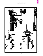
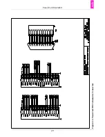
Страница 33: ...Panel Card Starterkit 27 Figure 6 2 Panel Card EVB Schematics USB RS232 ...
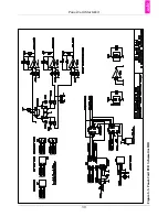
Страница 34: ...Panel Card Starterkit 28 Figure 6 3 Panel Card EVB Schematics Power Regulation ...
Страница 35: ...Panel Card Starterkit 29 Figure 6 4 Panel Card EVB Schematics Connectors ...
Страница 36: ...Panel Card Starterkit 30 Figure 6 5 Panel Card EVB Schematics HID ...
Страница 39: ...Panel Card Starterkit 33 Figure 6 8 Panel Card Connector Schematics USB Ethernet ...
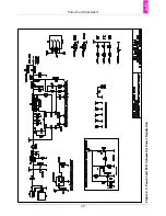
Страница 40: ...Panel Card Starterkit 34 Figure 6 9 Panel Card Connector Schematics Power Regulation Connectors ...
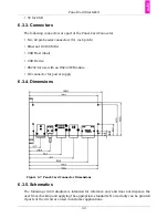
Страница 49: ...Panel Card Dimensions 43 Appendix H Panel Card Dimensions Figure H 1 Panel Card 35 Dimensions ...
Страница 50: ...Panel Card Dimensions 44 Figure H 2 Panel Card 57 Dimensions ...


