Hardware Description
12
4.14. Watchdog Timer
The watchdog timer is a 12-bit timer running at 256 Hz (Slow Clock / 128). The maximum
watchdog timeout period is therefore equal to 16 seconds. If enabled, the watchdog
timer asserts a hardware reset at the end of the timeout period. The application program
must always reset the watchdog timer before the timeout is reached. If an application
program has crashed for some reason, the watchdog timer will reset the system, thereby
reproducing a well defined state once again.
The Watchdog Mode Register can be written only once. After a processor reset, the
watchdog is already activated and running with the maximum timeout period. Once the
watchdog has been reconfigured or deactivated by writing to the Watchdog Mode Register,
only a processor reset can change its mode once again.
4.15. Peripheral DMA Controller (PDC)
The Peripheral DMA Controller (PDC) transfers data between on-chip serial peripherals
and the on- and/or off-chip memories. The PDC contains unidirectional and bidirectional
channels. The full-duplex peripherals feature unidirectional channels used in pairs
(transmit only or receive only). The half-duplex peripherals feature one bidirectional
channel. Typically full-duplex peripherals are USARTs, SPI or SSC. The MCI is a half duplex
device.
The user interface of each PDC channel is integrated into the user interface of the
peripheral it serves. The user interface of unidirectional channels (receive only or
transmit only), contains two 32-bit memory pointers and two 16-bit counters, one set
(pointer, counter) for current transfer and one set (pointer, counter) for next transfer. The
bidirectional channel user interface contains four 32-bit memory pointers and four 16-bit
counters. Each set (pointer, counter) is used by current transmit, next transmit, current
receive and next receive.
Using the PDC removes processor overhead by reducing its intervention during the
transfer. This significantly reduces the number of clock cycles required for a data transfer,
which improves microcontroller performance. To launch a transfer, the peripheral triggers
its associated PDC channels by using transmit and receive signals. When the programmed
data is transferred, an end of transfer interrupt is generated by the peripheral itself. There
are four kinds of interrupts generated by the PDC:
• End of Receive Buffer
• End of Transmit Buffer
• Receive Buffer Full
• Transmit Buffer Empty
The "End of Receive Buffer" / "End of Transmit Buffer" interrupts signify that the DMA
counter has reached zero. The DMA pointer and counter register will be reloaded from the
reload registers ("DMA new pointer register" and "DMA new counter register") provided
that the "DMA new counter register" has a non-zero value. Otherwise a "Receive Buffer
Full" or, respectively, a "Transmit Buffer Empty" interrupt is generated, and the DMA
Содержание Panel-Card
Страница 1: ...Panel Card Technical Reference ...
Страница 32: ...Panel Card Starterkit 26 Figure 6 1 Panel Card EVB Schematics Bus JTAG ...
Страница 33: ...Panel Card Starterkit 27 Figure 6 2 Panel Card EVB Schematics USB RS232 ...
Страница 34: ...Panel Card Starterkit 28 Figure 6 3 Panel Card EVB Schematics Power Regulation ...
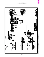
Страница 35: ...Panel Card Starterkit 29 Figure 6 4 Panel Card EVB Schematics Connectors ...
Страница 36: ...Panel Card Starterkit 30 Figure 6 5 Panel Card EVB Schematics HID ...
Страница 39: ...Panel Card Starterkit 33 Figure 6 8 Panel Card Connector Schematics USB Ethernet ...
Страница 40: ...Panel Card Starterkit 34 Figure 6 9 Panel Card Connector Schematics Power Regulation Connectors ...
Страница 49: ...Panel Card Dimensions 43 Appendix H Panel Card Dimensions Figure H 1 Panel Card 35 Dimensions ...
Страница 50: ...Panel Card Dimensions 44 Figure H 2 Panel Card 57 Dimensions ...


