37
2.4.1
Connections
Ensure that the outputs are switched off and that the device under test is isolated before
making any connections.
Connect the main outputs to the relay current coils as shown in figure 2.4. The output of phase
A is looped into the DVS3 mk2 phase lock input to allow the DVS3 mk2 to phase lock to the
current output of the 200A-3PH mk2.
Connect the output from the DVS3 mk2 to the relay voltage coils.
Set the AMMETER RANGE switch to 20A range, and the TIMER MODE switch to phase A.
Phase A of the DVS3 mk2 may be connected to the auxiliary input of the 200A-3PH mk2 as a
double-check on the phase angle if required. Refer to figure 2.4 for connections.
Connect the relay contacts to contacts set 1 on the DVS3 mk2.
2.4.2
Test procedure
– restraint angle
Set the output controls to zero (anti-
clockwise) and the timer mode to “off”.
Switch on the main output, and increase the output current for each phase to the setting
current of the relay.
Select “Phase lock” mode on the DVS3 mk2, and select the lock source as “External lock”.
Set the DVS3 mk2 to the desired output voltage, and switch the DVS3 mk2 output on. When
phase A on the DVS3 mk2 is set to zero, the voltage from the DVS3 mk2 will be in phase with
the current from the 200A-3PH mk2. The phase angle between the current and voltage may
now be altered using the phase control on the DVS3 mk2. The contacts on the relay will now
change state (indicated on the DVS3 mk2 screen) as the voltage phase is rotated through the
restraint angle of the relay.
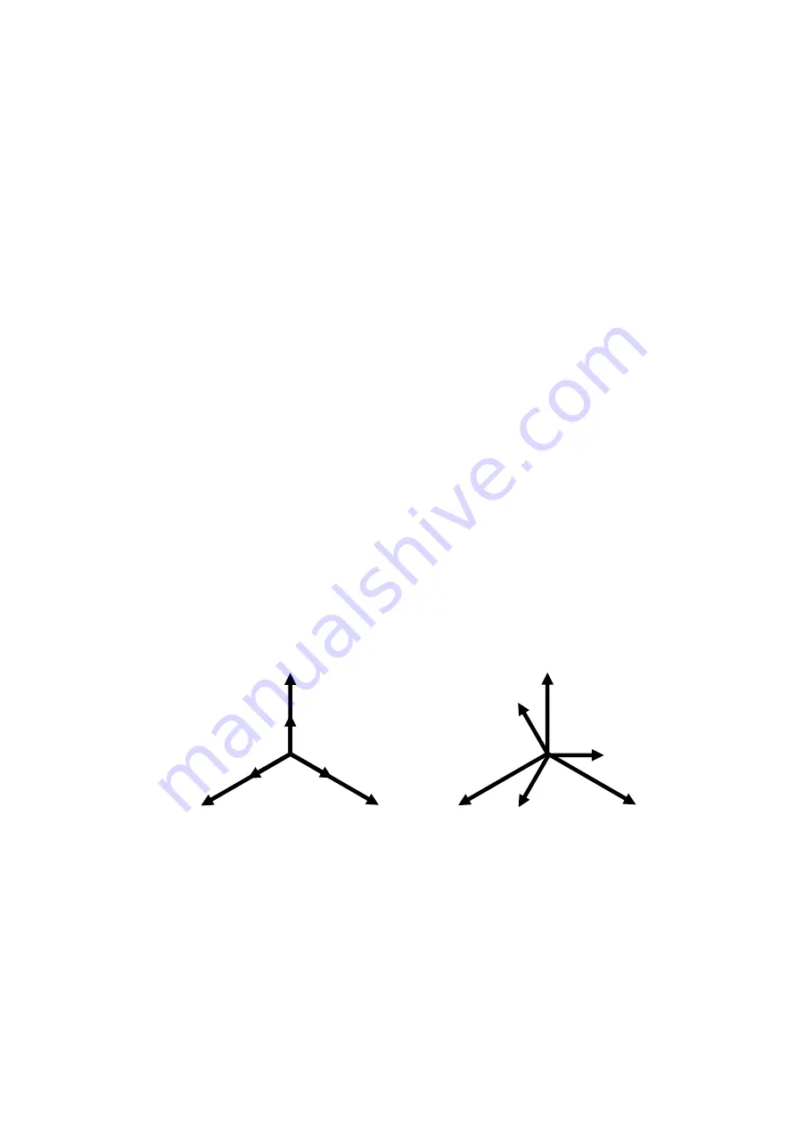
Figure 2.6 200A-3PH mk2 and DVS3 mk2 output phasors
DVS3 mk2 and 200A-3PH
mk2 in phase
V A
VB
VC
IA
IC
IB
DVS3 mk2 lagging 200A-3PH
mk2 by 30°
VA
VB
VC
IA
IB
IC
Содержание 200A-3PH mk2
Страница 4: ...4...
Страница 8: ......
Страница 45: ...45 Figure 5 3 Connections between units 3 WIRE SUPPLY OPTIONAL T R LINK LEAD...
Страница 48: ...48 8 DRAWINGS REQUIRED A2 001947 latest issue 200A 3PH mk2...


