background image

4-1

Chapter

4

Using the Administrator Tool

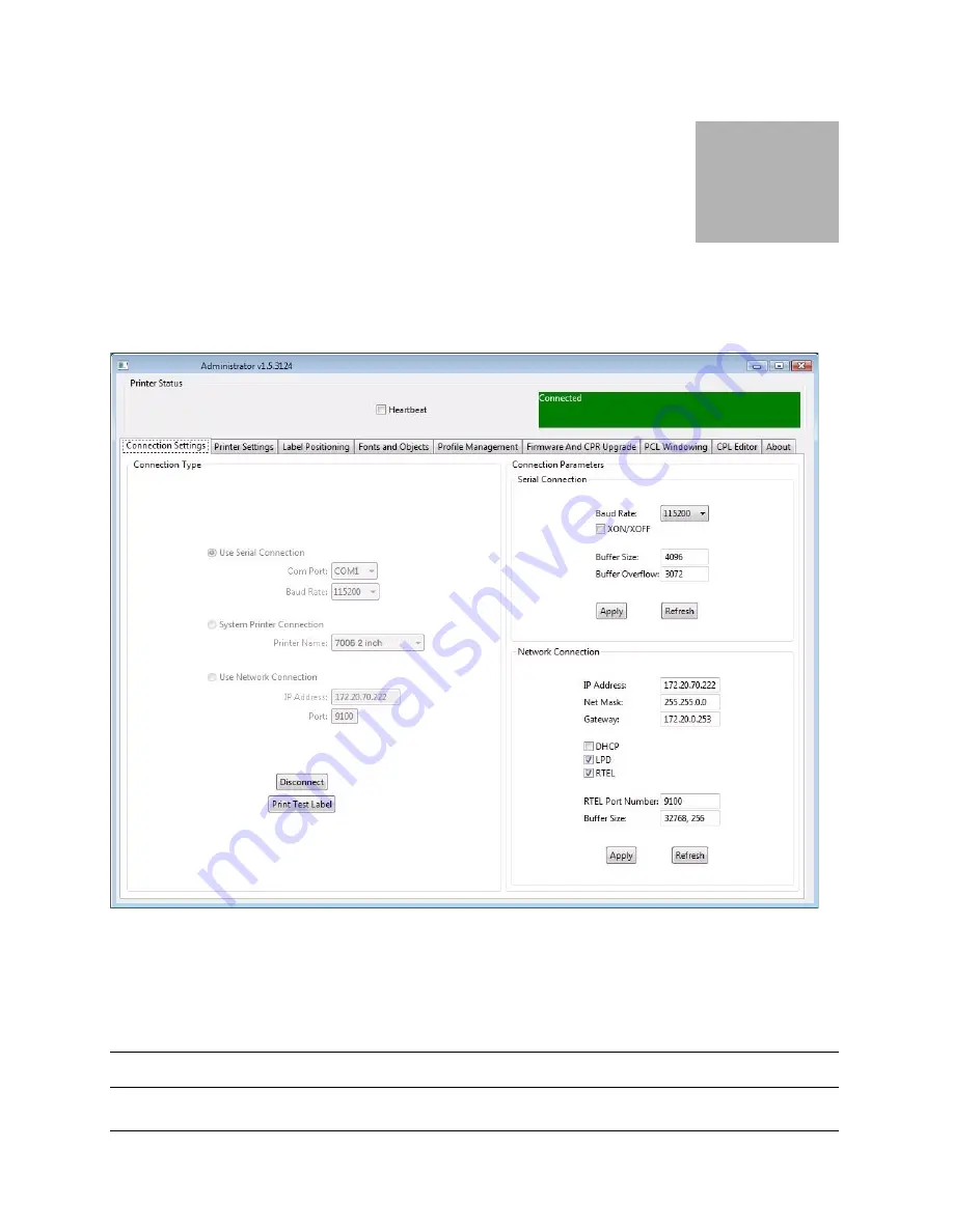
Select the connection method being used between computer and printer.

`

If using serial, select the appropriate communication port and baud rate.  The default 

serial baud rate is 9600.

`

If using USB, select the appropriate printer driver.

NOTE

: Refer to Chapter 3, “Windows Driver Installation” for more details.

Содержание 7006

Страница 1: ...User Guide 7006 7008 Thermal Printer ...

Страница 2: ......

Страница 3: ...Control Panel Buttons and the LCD 7008 only 2 8 Understanding the LCD Menu Structure 2 10 Setting Up the Printer 2 12 Printer Requirements 2 12 Unpacking the Printer 2 13 Controls Indicators and Connectors 2 14 Connecting Data Cables to the Printer 2 15 USB A HOST Connectivity 2 16 Connecting Power to the Printer 2 17 Printer Power Test 2 20 Thermal Transfer Ribbon Loading TT Printers Only 2 22 Lo...

Страница 4: ...ion software 4 3 Method 2 Calibrate by Performing a Self Test 4 3 Method 3 Calibrate Using the Programming Language CPL 4 3 Advanced Printer Settings 4 3 Fonts Objects 4 4 Profile Management 4 4 Firmware Upgrade 4 4 PCL Windowing 4 5 CPL Editor 4 6 USB A Host 5 1 Loading Firmware Using a USB Flash Drive 5 1 Loading firmware using the USB A Host 5 2 5 2 Network Printing 6 1 Assigning a Static Addre...

Страница 5: ...Test 8 1 Print a Proven Label Format 8 1 Print a New Label Format 8 2 Check the Label Format Header Line 8 2 Comment Out Portions of the Non Working Label Format 8 2 Common Issues 8 3 Labels Skipping or Printer Feeding Blank Labels 8 3 READY Light is Red 8 3 Printer Drivers 8 3 Setting Up an Ethernet Printer 8 3 Serial Communication 8 4 Parallel Communication 8 4 Printing Too Light 8 5 General Tro...

Страница 6: ...pecifications 9 5 Programming Language CPL 9 5 Communications Specifications 9 6 Electrical Specifications 9 6 International Environment Compliance 9 6 International Regulatory Compliance 9 6 Environmental Specifications 9 6 Physical Specifications 9 7 Software 9 7 Preventive Maintenance 9 7 Cleaning 9 7 Consumables 10 1 Compatible Media 10 1 Consumables 10 1 TT Butterfly Labels 10 6 DT Rattail La...

Страница 7: ...nce 11 1 Cleaning Instructions 11 1 Printhead Assembly Removal and Replacement 11 3 Printhead Assembly Removal 11 3 Printhead Assembly Replacement 11 5 Platen Assembly Removal and Replacement 11 8 Platen Assembly Removal 11 8 Platen Assembly Replacement 11 12 Index 1 1 ...

Страница 8: ......

Страница 9: ...s pro vided with every printer Chapter 2 Getting Started of this User s Guide provides fur ther instructions on setting up your printer Programmer s Guide The Programmer s Guide provides information about how to program all printer models For up to date firmware release notes and to download the most recent firmware required for the printers visit http jadmin dascom com Ethernet Printer Informatio...

Страница 10: ...W e l c o m e 1 2 Technical Support For technical support please contact your dealer or the Technical Support Team of your Tally Dascom Representatives see last page of this manual ...

Страница 11: ... and functions Parts and Functions Outside the Printer Figure 2 1 Top and Front View Device Use A CD control panel 7008 only Back lit two line 16 character display with full menus to change setup options B POWER LED Shows power status GREEN Power switch is turned on A B C D E F G H I J L M K ...

Страница 12: ...on Advances print media Enters user menu commands F Front bezel Covers the front of the printer G Lower case Covers the sides of the printer H Case base Covers the base of the printer I High lift printhead latches Pushes upward to release the printhead J ON OFF switch Controls printer power K Cast metal user interface cover Contains user interface buttons L Dust cover Protects print media M Hinged...

Страница 13: ...rge roll spindle slot Holds large roll media B Standard roll spindle slot Holds standard roll media C Cast metal user interface cover Contains user interface buttons D Printhead Printing mechanism E Printhead bracket Holds the printhead F Ribbon drive gear Feeds ribbon through the printer ...

Страница 14: ...n g S t a r t e d 2 4 Paper Media Guide Bar Figure 2 3 Inner Side View of Media Bar Figure 2 4 Top View of Media Guide from Behind Printer Device Use A Media guide silver bar Guides the labels through the printer ...

Страница 15: ...w Connector Use A ON OFF switch Controls printer power B Power connector Connects to power supply C Ethernet connector RJ 45 Ethernet communications port for network connectivity D USB B device port USB communications port E USB A host port USB communications port F Serial Parallel port Serial parallel data communications port ...

Страница 16: ... Clutch Gears Figure 2 6 Take Up Spindle Clutch and Side view of Clutch Gears Supply Spindle and Supply Clutch Figure 2 7 Supply Spindle and Clutch Components Description A Take Up Spindle B Take Up Clutch Components Description A Supply Spindle B Supply Clutch ...

Страница 17: ... S t a r t e d 2 7 Printhead Assembly TPH Shield Bracket and LED Array Figure 2 8 Printhead Assembly Platen and Index Sensor Figure 2 9 Platen Assembly and Index Sensor Components Description A Index Sensor B Platen ...

Страница 18: ...ncountered To begin navigation through the menu press the RIGHT button to enter the MAIN MENU Pressing the UP DOWN buttons and the ENTER button allows movement throughout the menu tree Pressing the ENTER button selects a menu item allowing navigation deeper into that menu At any time the LEFT button may be pressed to return to the previous menu level or to escape without making a selection Repeate...

Страница 19: ...r certain menu items ENTER button E In the menu mode selects a menu item for further navigation ENTER also selects a value in a menu item The LCD displays the confirmation message VALUE HAS BEEN SET At the highest menu level when the manufacturers name is displayed on the LCD or when the printer is ready to print this button acts as a FORM FEED When the ENTER button is pressed a single label is fe...

Страница 20: ...SETUP MENU COMM Menu Serial BAUD 1200 2400 4800 9600 19200 38400 57600 115200 PARITY Even Odd None DATA Bits 7 or 8 STOP Bits 1 or 2 Ethernet DHCP ON or OFF Set Static IP XXX XXX XXX XXX Set Subnet XXX XXX XXX XXX Set Gate way XXX XXX XXX XXX Transfer Mode Direct Thermal or Thermal Transfer Speed High Normal Low DPI Select 200dpi Selectable 200 or 100 dpi or 300dpi Selectable 300 or 150 dpi Index ...

Страница 21: ...2 Label Print Timeout 0 65535 Quick UP DWN key press increments by 1 Press and hold increments by 10 CALIBRATION MENU Calibration Menu Start Based on Bar Gap or Notch index setting TEST MENU Label or Objects OPTIONS MENU External 5 volts ON or OFF SETTINGS MENU Save Settings Yes Or No Read Settings Yes Or No Factory Defaults Yes Or No CUSTOMER SUPPORT For technical support please contact your deal...

Страница 22: ...nter has the following operational requirements Communications Serial Standard RS 232 requires a custom cable refer to Chapter 10 Parallel Uni directional parallel interface requires a custom cable refer to Chap ter 10 USB A Host Interface USB cable MSD HID USB B 2 0 Device Interface USB cable Ethernet 10 100 Optional Standard 10Base T Cat 5e interface cable Auto detectable 90 264VAC 24VDC 150 W p...

Страница 23: ...G e t t i n g S t a r t e d 2 13 Unpacking the Printer Figure 2 11 Packaging Diagram Power cord Power supply Printer Accessories ...

Страница 24: ...tion Use A POWER light Shows power status ON printer on and ready to print OFF no power applied B READY indicator Shows printer status GREEN printer ready to accept data RED printer error empty media roll or paused operation during batch mode processing OFF no power applied C FEED button Advances print media Press to advance media Press and hold while turning unit on to initiate self test and prin...

Страница 25: ...d parallel or serial cable will not work with this printer To obtain more information on how to order a custom serial and or parallel cable compatible for the printer please refer to Chapter 10 Consumables of this user s guide A standard USB cable is shipped with the printer It is located in the accesso ries box Connector Use A ON OFF switch Controls printer power B Power connector Connects to pow...

Страница 26: ...drives These devices can be used to input data directly to the printer They are most commonly used in conjunction with CPL scripting language for example menus and stored formats to produce labels The USB flash drive can be used upgrade printer firmware This topic is discussed fur ther in Chapter 5 Loading Firmware Using a USB Flash Drive ...

Страница 27: ...er supplied with the printer Using a power adapter not certified for use is both unsafe and voids the war ranty on the printer IMPORTANT NOTE Follow these steps in order to safely connect power to the printer 1 Connect the provided power supply cord into the power supply unit Figure 2 14 Connecting the Power Cord into the Power Supply ...

Страница 28: ... the printer The flat end of the power supply cord listed as B below in Figure 2 15 has an arrow to indicate which end is on top There is also an indented key shown as A below in Figure 2 15 to illustrate which end should be inserted upright into the power connector Figure 2 15 Connecting the Power Supply to the Printer ...

Страница 29: ...into the power source by carefully plugging the power cord into the wall outlet or other power source NOTE Once the power supply is plugged into the wall the green LED illumi nates on the power supply unit Figure 2 16 The Green Power Light on the Power Supply ...

Страница 30: ... when the printer is ready to print Figure 2 17 Powering ON the Printer Device Primary Function Use A POWER light Shows power status ON printer on and ready to print OFF no power applied B READY indicator Shows printer status GREEN printer ready to accept data RED printer error empty media roll or paused operation during batch mode processing OFF no power applied C FEED button Advances print media...

Страница 31: ...bout one second When the printer is ready to print the LCD displays Tally Dascom see Figure 2 18 below Figure 2 18 LCD Display 5 Press the Power Switch to OFF and confirm the Power and Ready Light turn off before proceeding to the next steps Refer to Figure 2 12 in step 1 of the Power Test section of this manual to locate the power button on the printer ...

Страница 32: ...structions on how to load thermal transfer ribbon into the printer There is a ribbon loading label on the side of the printhead mechanism for all thermal transfer printers as shown in Figure 2 19 below Figure 2 19 Ribbon Loading Label For ribbon specifications and details please refer to the Consumables Guide on the Instal lation CD or the manufacturers web site 1 Lift the top hinged dust cover Fi...

Страница 33: ...e Test Sample from the Printer 3 Place the sample ribbon provided with the printer in front of the printer for loading Place the large media end towards the printer with the small take up roll end facing away from the printer as shown in Figure 2 22 below Gently remove the tape off the ribbon to prepare for ribbon loading Figure 2 22 Removing Tape Off of the Ribbon ...

Страница 34: ... the ribbon does not roll off the table when setting it down Figure 2 23 Ribbon Layout Before Loading Into the Printer 5 Next unlatch the printhead mechanism to load the ribbon into the printer To do this pull up on the black latches with both hands Refer to the figure below to release the printhead mechanism Figure 2 24 Unlatching the Printhead Mechanism ...

Страница 35: ...r t e d 2 25 6 Next raise the printhead mechanism fully Refer to the figure below Figure 2 25 Fully Raised Printhead Mechanism CLEANING NOTE This is the ideal position for cleaning the printhead printhead shield and platen ...

Страница 36: ...currently is positioned with the leader text showing Examine the ends of the ribbon supply roll and notice the notches on the roll These notches fit into the printer Refer to Figure 2 27 for clear pictures of the notches Figure 2 26 Ribbon Supply Core Notches Figure 2 27 Lining up the Ribbon Supply Core Notches with the Supply Spindle Notches ...

Страница 37: ...roll into place Figure 2 28 Pulling Out the Ribbon Supply Spindle 9 Place the ribbon supply roll into position as shown in Figure 2 29 below Line up the notches on the ribbon supply roll with the printer supply spindle tabs to secure the ribbon supply roll into place Figure 2 29 Lining up the Supply Roll Core with the Ribbon Spindle tabs ...

Страница 38: ...igure 2 30 Supply spindle Rotation to Secure Supply Roll In Place 11 Once the ribbon supply roll is loaded gently lower the printhead mechanism down with one hand while holding the user interface cover with the other hand DO NOT LATCH the printhead mechanism Refer to Figure 2 31 Figure 2 31 Separating and Lowering the Printhead Mechanism from the User Interface Without Latching the Mechanism ...

Страница 39: ...elease the printhead mechanism as shown in Figure 2 24 12 Next install the ribbon take up roll Examine the ends of the ribbon take up core and notice the notches on the ribbon core These notches fit into the printer Refer to Figure 2 32 for clear pictures of the notches Lift the ribbon take up roll as shown in the figures below Figure 2 32 Take up Roll Notches and Loading the Take Up Roll ...

Страница 40: ...ecure the take up roll into place Figure 2 33 Pulling the Take Up Spindle Out to Insert Take Up Roll 14 Place the ribbon take up roll into position as shown in Figure 2 34 Once the ribbon feels secure gently push and rotate the green take up spindle clockwise to make sure the ribbon take up core is engaged with the notches on the printer Figure 2 34 Seating the Ribbon Take Up Core Into the Take Up...

Страница 41: ...otate the green take up spindle clockwise until the black ribbon begins winding on the take up core as shown in Figure 2 35 Figure 2 35 Winding the Ribbon Onto the Take Up Core 16 Gently lower the user interface but DO NOT LATCH the printer Refer to Figure 2 36 Figure 2 36 Lowering the User Interface without Latching the Mechanism Set User Interface Down DO NOT LATCH ...

Страница 42: ...approved media please contact a local reseller or the manu facturer 1 Lift the top dust cover Thermal Transfer printers have already completed this step in the ribbon loading section Figure 2 37 Lifting the Dust Cover 2 Remove the Manufacturing Test Sample from inside the printer and file the Manu facturing Test Sample with the other documentation for future reference Thermal Transfer printers hav...

Страница 43: ...roll see inward and outward wound media figures below Figure 2 39 Inserting the Spindle Into the Approved Inward Wound Media Figure 2 40 Inserting the Spindle into Outward Wound Media NOTE For more information regarding approved media please contact a local reseller or the manufacturer ...

Страница 44: ...rovide proper media control during printing The right media guide has a green locking tab as shown in Figure 2 41 that holds the guides in any position This is useful if the same width media is often used Once the guide is set to the width of the media it can be locked in place and future loading of media is simplified Figure 2 41 Media Guide Locking Tab ...

Страница 45: ...e of the printer as shown in Figure 2 42 Figure 2 42 Spread the media guides apart NOTE The lock can be removed if it is pulled up too hard If this happens re insert the lock in the media guide 6 Locate the media guide bar in the rear of the mechanism indicated by the arrow in Figure 2 43 below The media must be placed under the media guide bar or media wandering can occur Figure 2 43 Top View of ...

Страница 46: ...oll a few labels Position the media print side up into the printer as shown in Figure 2 44 and 2 45 Figure 2 44 Media Print Side Must be Facing Up for Inward Wound Media Figure 2 45 Media Print Side Must be Facing Up for Outward Wound Media ...

Страница 47: ...er the Media Guide Bar 9 Lower the media between the two media guides Position the media as shown in Fig ure 2 47 Before completely lowering the spindle in the slots as shown unlock the guides if they are locked so they can spring load against the sides of the media roll Figure 2 47 Lower the Media Roll Into Lower Media Guide Slots ...

Страница 48: ...push the roll down in the slot as shown in Figure 2 48 This locks the media guide in the proper position The media should look as shown Figure 2 48 Push Down on the Right Side of the Roll to Lock the Media Guide 11 Lift the mechanism as shown in Figure 2 49 Figure 2 49 Lift the Mechanism ...

Страница 49: ... 2 50 Front View of Media Being Loaded Under Media Guide 13 Pull the media forward three to four inches from within the mechanism past the drive platen as shown in Figure 2 51 Center the media on the platen before pro ceeding to the next step Figure 2 51 Pulling the Media Three to Four Inches then Centering on the Platen ...

Страница 50: ...14 Once the media is pulled forward three to four inches latch the mechanism as shown in Figure 2 52 Figure 2 52 Latching the Mechanism 15 Close the dust cover to enclose standard size media while printing Figure 2 53 Closed Dust Cover ...

Страница 51: ...ear of the printer as identified with the arrows in Figure 2 54 Remove the screws with a 2 Phillips screwdriver Keep the screws for future usage Figure 2 54 Rear Door Screws Identified by Arrows 2 Open the rear door and leave it in the position shown in Figure 2 55 Figure 2 55 Open Rear Door as Shown ...

Страница 52: ...G e t t i n g S t a r t e d 2 42 3 Open the media covers as shown in Figure 2 56 Figure 2 56 Loading Large Media Roll Print Side Up Figure 2 57 Large Media Roll in Position ...

Страница 53: ...G e t t i n g S t a r t e d 2 43 4 Close the top cover and let the dust cover rest on the large media roll Figure 2 58 Closing the Top Cover ...

Страница 54: ... IMPORTANT The printer should be loaded with media connected to AC power and turned on 1 Press and hold the FEED button 2 Turn the printer ON while holding the FEED button 3 Release the FEED button when the self test starts to print 4 Turn the printer off and then on again to return to normal printing operation IMPORTANT After performing the self test the printer is in hexadecimal dump mode and ca...

Страница 55: ... Density Energy Offset 0 0 Feed Speed Speed at which media is fed using the FEED button Feed Speed NORMAL Index Enabled Current state of Indexing Either enabled or disabled No Index Index Enabled Feed Type Current Indexing mode GAP BAR or Notch Feed Type GAP DTBAR Index sensor settings for Black Bar indexing in Direct Thermal print mode DTBAR R 56 T 13 G 0 TTBAR Index sensor settings for Black Bar...

Страница 56: ...cates direct thermal printing TT indi cates thermal transfer printing Print Mode DT TT Print Speed Displays the current printing speed setting Print Speed HIGHSPEED Report Level Sets the manner in which the printer reports recoverable errors Report Level 2 Shift left 1 100 inches Distance the image is shifted to the left in hundredths of an inch Shift left 1 100 inches 0 Text Buffer Size Size of t...

Страница 57: ...he required software for the printer When the installation is complete proceed to Chapter 4 of this User s Guide METHOD B Install Software Using the Web Site Our web site http jadmin dascom com will be permanently updated with the newest version of software and documentation You are able to find the following data Printer driver Install the printer driver software Administrator Tool Install the Ad...

Страница 58: ...printer 9 The printer will be available in your windows system Setting Printing Preferences The printer driver must be configured for the user s specific needs Use the following steps to set the default printer driver preferences 1 Click Start 2 Click Settings and choose Printers and Faxes 3 Right click on the printer icon and choose Properties from the shortcut menu The Properties dialog box appe...

Страница 59: ...or configuration software allows the user to configure test and operate the printer Installing the Administrator Configuration Software 1 Navigate to the temporary folder the file was copied 2 Double click the CAdminInstall exe file The InstallShield Wizard starts 3 Please follow the instruction on the screen ...

Страница 60: ......

Страница 61: ...od being used between computer and printer If using serial select the appropriate communication port and baud rate The default serial baud rate is 9600 If using USB select the appropriate printer driver NOTE Refer to Chapter 3 Windows Driver Installation for more details ...

Страница 62: ...list Select the apply button to send the new setting to the printer Selecting the Refresh button will refresh the printers current settings to verify the new change Administrator Sections The Administrator is divided into tabs Each tab represents different abilities that the software provides Below is a brief description I O Settings Controls Host PC to Printer communication options Printer Serial...

Страница 63: ...e text Press Feed Switch Now to Calibrate Index will appear on the media Press the Feed switch at this time to perform the calibration Once completed the Printer must be power cycled to return to its proper printing state If calibration was successful pressing the Feed button will eject only one label at a time Method 3 Calibrate Using the Programming Language CPL Calibration may also be performed...

Страница 64: ...rinter s current profile select Get Current Printer s Profile The printer will display its settings To save the printer s profile to a file select Save Profile to File This creates a text file with a pfl extension This profile can later be opened and sent to other printers connected to the Administrator To open a previously saved file select the Open Stored Profile To apply the displayed profile t...

Страница 65: ...er the upper left corner coordinates of the desired windowed area you wish to print from your original image View the page in portrait orientation when performing this operation Enter the length and width of the label you ll be using to print on with your printer A test print will appear to ensure your label size settings are correct The box printed should fit within the edges of your label Test y...

Страница 66: ... files and send them to the printer To send a file to the printer either type the information in the Printer Input side or select Open File select the file and select OK To send the data to the printer select Send to Printer Any response that the printer returns will be displayed in the Printer Indications section To save any printer response select Save Output To clear the response select Clear O...

Страница 67: ...and deter mines if the drive contains a firmware upgrade Figure 5 1 Connections Including the USB A Host Port Connector Use A ON OFF switch Controls printer power B Power connector Connects to power supply C Ethernet connector RJ 45 Ethernet communications port for network connectivity D USB B device port USB communications port E USB A host port USB communications port F Serial Parallel port Seri...

Страница 68: ...y and finally reboots At this time the new firmware is loaded and executed in the printer NOTES The printer will only read the contents of the usb flash drive if it is inserted after the printer is ready Do not modify the firmware file name as distributed by the manufacturer The printer uses the filename to know whether the firmware image contained in the file represents an upgrade Changing the fi...

Страница 69: ...etermine the printer s address on the network One is to assign the printer an address by entering it in this settings window and the other is to allow the network to automatically assign an address to the printer Assigning a Static Address To assign a static address first obtain an address from the network administrator In addition to the address for the printer the network administrator must repo...

Страница 70: ...gs area It is not necessary to enter any addresses in the fields above In addition to the DHCP check box select the LPD and RTEL check boxes Type 9100 in the RTEL Port Number field and type 32768 in the Ethernet Text Buffer Size field For the printer to receive its address from the network it must be connected to the net work when it is turned on If the printer is not connected to the network when...

Страница 71: ...a test label by clicking the Print Self Test Label button at the bottom right of the I O Settings tab The network settings are printed near the end of the test label Once the network settings are made disconnect the printer from the USB serial parallel port both physically and in the Administrator It is possible to physically relocate the printer and still be able to communicate with it as long as...

Страница 72: ...nt using the driver a new port must be configured within the printer driver 1 Locate the appropriate driver in the Windows Printers folder 2 Right click on the driver and select Properties 3 Click on the Ports tab 4 Choose Add Port 5 Highlight Standard TCP IP Port and click New Port 6 Click Next ...

Страница 73: ...ame or IP Address box enter the IP address assigned to the printer The Port Name box is auto populated Click Next 8 If necessary choose Generic Network Card as shown below and then click Next 9 Click Finished The driver is now configured and ready to use ...

Страница 74: ... the Windows Printers folder 2 Right click on the driver and select Properties 3 Click on the Sharing tab 4 Select Share this printer and give the printer a Share name 5 Once a share name has been typed click Apply Network Support Materials NOTE For more information on configuring Ethernet settings on the printer please refer to the Ethernet Printing Information section of the Programmer s Guide ...

Страница 75: ...d terminate printing operation To begin start the Administrator program and connect to the printer see Chapter 4 Using the Administrator Tool After connecting to the printer select the CPL Editor tab and enter the following text in the Printer Input text area on the left 0 100 100 1 WIDTH 224 PITCH 200 DRAW_BOX 20 0 200 30 2 TEXT 2 20 0 TEST LABEL BARCODE CODE39 20 70 40 1234567894567 END This ser...

Страница 76: ...e l s a n d T a g s 7 2 To save this label format for future use click the Save to File button To reload it or any other label format click the Open File button For more detail on the CPL language please refer to the CPL Programmer s Guide ...

Страница 77: ...ls using Microsoft Word software The instructions assume the following conditions The user has a basic understanding of Microsoft software and the Windows operating system Printer drivers are installed correctly The printer is connected powered on and ready to print NOTE Examples shown here were created using Microsoft Windows XP and Microsoft Word 2002 To Configure the Software for the Printer 1 ...

Страница 78: ...P r i n t i n g S t a n d a r d L a b e l s a n d T a g s 7 4 3 Select a printer 4 Click Close to close the Print dialog box ...

Страница 79: ...n g S t a n d a r d L a b e l s a n d T a g s 7 5 Setting Label Size Set up the Word document for the desired label size 1 On the File menu click Page Setup The Page Setup dialog box displays 2 Set all margins to 0 ...

Страница 80: ...P r i n t i n g S t a n d a r d L a b e l s a n d T a g s 7 6 3 Click the Paper tab 4 Set the correct width and height for the label The example shows a 2 4 wide by 1 tall label ...

Страница 81: ...P r i n t i n g S t a n d a r d L a b e l s a n d T a g s 7 7 5 Click OK and if necessary Fix to reset the margins The Word document should look similar to the figure below ...

Страница 82: ...ll not display on the screen but is printed on the label 3 Set the height of the barcode by adjusting the font size Use trial and error to adjust the size correctly Printing a Label Make sure that the printer is connected to the computer and powered on Ensure that the media is loaded correctly Use the following steps to print the label 1 Press Ctrl P or on the File menu choose Print The Print dial...

Страница 83: ...ecific Some of these require a generic text printer driver Others have built in printer drivers Refer to the software documentation or contact the software vendor to determine the appropriate method for printing labels with proprietary software NOTE Apart from the CPL emulation there are some other emulations available for the printer e g the ZcPL EcPL PcCl emulations ...

Страница 84: ......

Страница 85: ...orming the Self Test NOTE Leaving the printer in hex dump mode following a self test allows the user to see every character that reaches the printer Use of hex dump mode can help resolve some programming problems If the printer will not print a self test label the problem is most likely hardware related and the printer will not respond to incoming data In this case please contact technical support...

Страница 86: ...urs in the header line Refer to the Programmer s Guide header line section before continuing Comment Out Portions of the Non Working Label Format Improper printer commands can be isolated by placing a C before selected CPL com mand lines Begin by commenting out the most complex lines first and try printing the format again If the problem persists try commenting out every line between the header li...

Страница 87: ...n of Chapter 4 Calibrating the Printer Make sure that the correct power supply for the printer is being used The printer uses a 90 264VAC output power supply The output voltage is printed on the power supply Printer Drivers Printer drivers are available for download from the manufacturers web site For more information on where to download printer drivers please reference Chapter 3 Windows Driver I...

Страница 88: ... a serial port will be used for printing to the printer a custom null modem serial cable from the manufacturer is required Refer to the accessories section listed in Chapter 10 Consumables or the Printer Product Guide for ordering information The default serial communications settings are 9600 N 8 1 Parallel Communication If a parallel port will be used for printing to the printer a custom uni dir...

Страница 89: ...arker the print will be Send this file to the printer by selecting File then selecting Print The printer will not print anything but the ready light will blink on and off Once a solid Green ready light is visible cycle the power to the printer To verify the settings have taken effect perform a self test and verify the settings are now set in the printer For more instructions on per forming a self ...

Страница 90: ...rding suggesting cleaning and preventive maintenance NOTE Do not use blades sharp tools etc to prevent damage to the rubber platen Tips for Avoiding Paper Jams Make sure the roll of media is aligned in the center of the printer and the printer s spring loaded media guides are firmly pressed against both sides of the roll Blank Label is Printing Make sure all cables and connectors are installed and...

Страница 91: ...tion Standard Features Compact printer design small footprint high performance Administrator Configuration Software Bi directional USB Drivers LCD control panel Back lit 2 line 16 characters 7008 only 200 MIPS 180MHz 32 bit RISC Processor 16 MB SDRAM memory 8 MB flash memory for firmware and stored objects Hinged media cover to accommodate oversized rolls Double clamshell design for easy access us...

Страница 92: ...ems Optional Features 300 dpi Print Resolution 12 dots mm Ethernet 10 100 Base T interface Thermal Transfer Printing PCL 4 printers with 300 dpi printhead only Printing Specifications Nominal Printer Size 2 7006 or 7008 4 7006 or 7008 Print Resolutions 203 dpi Standard 300 dpi Optional 203 dpi Standard 300 dpi Optional Max Print width 2 118 53 8mm 2 205 56 0mm 4 094 104 0mm 4 153 105 5mm Print Spe...

Страница 93: ... 5 12 7mm to 2 84 72mm 4 Printer 2 4 60 96mm to 4 63 117 6mm Minimum label length 0 375 9 5mm with 125 gap Maximum media roll size 7 750 194mm O D on a 1 5 38 1mm ID Core Media Indexing Indexing Sensing Methods None gap bar notch and hole Gap and notch sensing standards Minimum Inter label gap 0 125 3 18mm Gap Sensing Width Range 2 Printer User adjustable 1 right of center to 1 2 left of center 4 ...

Страница 94: ...er Ribbon 7 Label Roll OD equivalent to 8 Roll Font Specifications Bitmapped 7 styles with up to 10x10 magnification variable boldness and spacing International AGFA Fonts Sans serif font in 7 pt sizes up to 4x4 magnification vari able boldness and spacing Scalable Vector Fonts 3 ultra font styles for smooth characters in any size and bold ness Rotations 0 90 180 270 degrees Label Roll OD Label Ro...

Страница 95: ...e graphics and bitmap fonts Automatic serialization of fields Format inversion white on black Four position field rotation 0 90 180 270 Programmable label quantities with print and pause control Status messages to host upon request UPCA ADD 2 EAN 8 128C UPCE ADD 5 EAN 13 CODE128 UPCE1 CODE 39 PLESSEY EAN128 POSTNET I 2OF5 128A CODABAR Maxicode mode 0 CODE 93 128B MSI PDF417 DataMatrix QR Code Azte...

Страница 96: ...nterface Cat 5e cable Optional Electrical Specifications Auto detectable 90 264VAC 24VDC 150W power supply International Environment Compliance Compliant with the following international environmental directives Directive 2002 95 EC on the restriction of Use of certain Hazardous Substances in Elec trical and Electronic Components RoHS Directive 2002 96 EC on Waste Electrical and Electronic Equipme...

Страница 97: ...h a lint free cloth and if necessary a mild detergent solution in a damp cloth It is recommended that interior components are cleaned with authorized cleaning supplies every 20 000 inches 508 m or blown air to remove any particles The printhead should be cleaned every 5000 inches if preprinted labels are used The platen should be cleaned at the same interval using the same cleaning materials as ap...

Страница 98: ......

Страница 99: ...capabilities from sequential numbering and barcodes to full color labels The manufacturer uses only the highest quality facestocks and adhesives A wide range of paper cardstock and synthetic film materials for thermal printers along with special ized materials Adhesives ranging from super aggressive to ultra removable plus spe cialty adhesives that can withstand extreme The manufacturer has a full...

Страница 100: ... 1041 1 5x1 1 DT Vinyl Permanent In 3 5 1 5 750 12 Bar N 03 89 1037 1 5x3 1 DT Paper Permanent In 3 5 1 5 280 12 Bar N 03 89 1040 1 5x3 1 DT Vinyl Permanent In 3 5 1 5 280 12 Bar N 03 89 1036 2x 56 1 DT Paper Permanent In 4 75 1 5 2665 12 Gap N 03 02 3006 2x0 56 1 DT Paper Permanent In 4 75 1 5 2665 12 Bar N 03 02 1368 2x1 1 DT Paper Permanent In 3 1 5 880 36 Gap N 03 02 2611 2x1 1 DT Vinyl Perman...

Страница 101: ... DT Paper Permanent In 5 1 5 2480 12 Gap N 03 02 2114 3x1 1 DT Paper Permanent In 7 1 5 5600 6 Gap N 03 02 2604 3x1 1 DT Paper Permanent In 4 75 1 5 1775 12 Gap N 03 02 1821 4 25x1 1 DT Paper Permanent In 5 1 5 2350 12 Gap N 03 02 2117 4 25x1 1 DT Paper Permanent In 7 1 5 5305 6 Gap N 03 02 2602 4 25x1 1 DT Paper Permanent In 2 75 400 12 Gap N 03 02 1391 4 25x1 1 DT Paper Permanent In 4 75 1 5 168...

Страница 102: ...1 5 484 12 Gap N 03 02 2557 4x4 1 DT Paper Permanent In 7 1 5 1525 6 Gap N 03 02 2594 4x6 1 DT Paper Permanent In 5 1 5 455 12 Gap N 03 02 2116 4x6 1 DT Paper Permanent In 7 1 5 1025 6 Gap N 03 02 2592 4x6 1 DT Paper Permanent In 4 75 1 5 326 12 Gap Y 03 02 1827 2610012 4 25x6 1 DT Paper Permanent In 2 75 75 12 Gap N 03 02 1393 4 25x6 1 DT Paper Permanent In 4 75 1 5 323 12 Bar N 03 90 1054 4 25x6...

Страница 103: ...nent In 4 75 1 5 1685 12 Gap N 03 02 1830 2 4x1 1 TT Vinyl Permanent In 5 1 5 2270 12 Gap N 03 02 2130 2 4x1 1 TT Vinyl Permanent In 7 1 5 4800 6 Gap N 03 02 2579 2 4x1 1 TT Vinyl Permanent In 4 75 1 5 1685 12 Gap Y 03 02 1733 2610011 2 4x1 1 TT Vinyl Permanent In 4 75 1 5 1685 12 Gap N 03 90 1046 2 4x2 1 TT Paper Permanent In 5 1 5 1280 12 Gap N 03 02 2124 2 4x2 1 TT Paper Permanent In 7 1 5 2880...

Страница 104: ...e Wind OD Core Items per roll Rolls per case Index Stock item Roll Part 2x 56 1 DT Vinyl Permanent In 4 75 1 5 2665 12 Gap N 03 02 1797 2x 56 1 DT Vinyl Permanent In 4 75 1 5 2665 12 Bar N 03 02 1649 2x 56 1 DT Vinyl Permanent In 4 75 1 5 2665 12 Bar N 03 89 1024 2x 56 1 DT Vinyl Permanent In 5 1 5 3600 12 Gap N 03 02 2113 2x 56 1 DT Vinyl Permanent In 7 1 5 7600 6 Gap N 03 02 2574 Size WxH across...

Страница 105: ...2 25x1 1 DT Vinyl Permanent In 4 75 1 5 1685 12 Bar N 03 50 0041 3 5x 4375 1 DT Vinyl Permanent In 4 75 1 5 3100 12 Gap N 03 50 0043 Size WxH across Print type Material Adhesive Wind OD Core Items per roll Rolls per case Index Stock item Roll Part 1 25x3 1 DT Vinyl Permanent In 4 75 1 5 640 12 Bar N 03 02 3000 2 25x1 1 DT Vinyl Permanent In 4 75 1 5 1685 12 Bar N 03 50 0041 3 5x 4375 1 DT Vinyl Pe...

Страница 106: ...03 02 1867 2 4x2 1 DT 7 5 mil In 5 1 5 1050 12 Bar N 03 02 2109 2 4x2 1 DT 7 5 mil In 5 1 5 1050 12 Gap N 03 02 2110 2 4x2 1 DT 7 5 mil In 7 1 5 2400 6 Bar N 03 02 2576 2 4x2 1 DT 7 5 mil In 7 1 5 2400 6 Gap N 03 02 2572 Size WxH across Print type Thickness Wind OD Core Items per roll Rolls per case Index Stock item Roll Part 2 4x1 1 TT 12 mil In 4 75 1 5 996 12 Bar N 03 91 1087 2 4x1 1 TT 7 5 mil...

Страница 107: ...er Permanent In 4 75 1 5 1250 12 Gap Y 2600044 101x76 1 DT Top Coated Paper Permanent In 4 75 1 5 1000 12 Gap Y 2600045 101x152 1 DT Top Coated Paper Permanent In 4 75 1 5 500 12 Gap Y 2600046 25x25 1 DT Uncoated Paper Permanent In 4 75 1 5 2500 12 Gap Y 2600047 38x25 1 DT Uncoated Paper Permanent In 4 75 1 5 2500 12 Gap Y 2600048 38x38 1 DT Uncoated Paper Permanent In 4 75 1 5 1750 12 Gap Y 26000...

Страница 108: ... 75 1 5 1250 12 Gap Y 2600026 101x76 1 TT Matt Velum Paper Permanent In 4 75 1 5 1000 12 Gap Y 2600027 101 6x152 4 1 TT Matt Velum Paper Permanent In 4 75 1 5 500 12 Gap Y 2600028 25x25 1 TT Semi Gloss Paper Permanent In 4 75 1 5 2500 12 Gap Y 2600029 38x25 1 TT Semi Gloss Paper Permanent In 4 75 1 5 2500 12 Gap Y 2600030 38x38 1 TT Semi Gloss Paper Permanent In 4 75 1 5 1750 12 Gap Y 2600031 50x2...

Страница 109: ...e in harsh environmental conditions Width Inches Length Inches Formulation Printer Compatibility Rolls per case Part 4 2 3156 Wax 7005 12 2610008 4 2 3156 Wax Resin 7005 12 2610019 4 2 3156 Premium Resin 7005 12 2610021 2 4 6500 Wax 7006 7008 12 2610000 4 2 6500 Wax 7006 7008 12 2610001 2 4 6500 Wax Resin 7006 7008 12 2610014 4 2 6500 Wax Resin 7006 7008 12 2610015 2 4 6500 Premium Resin 7006 7008...

Страница 110: ...lease refer to the Installation CD or the web site Printer Options Product Model Description 2 4 DT TT 3600000 Parallel cable 9 9 9 9 3600004 Serial cable 6 9 9 9 9 3600005 Serial adapter for 5VDC 9 9 9 9 3600006 USB Cable 9 9 9 9 3600015 Spindle 2 9 9 9 3600016 Spindle 4 9 9 9 ...

Страница 111: ...e swabs etc Cleaning Instructions The exterior is cleaned with a lint free cloth and if necessary a mild detergent solution Interior components printhead platen roller media sensor peel bar ribbon and media paths are cleaned with a 98 to 99 pure isopropyl or denatured alcohol or blown air to remove any particles The printhead should be cleaned every 5 000 inches if pre printed labels are used Figu...

Страница 112: ...efore turning the printer back on Figure 11 2 Cleaning the Printer Parts 2 Clean the printhead A platen B and the index sensors C and D with a soft lint free cloth saturated with 99 percent isopropyl alcohol 3 Turn the printer on and press the FEED button to clean all sides of the roller CAUTION Incorrectly cleaning the printer will cause permanent damage and void the printer s warranty ...

Страница 113: ...or authorized field technician All user s must not replace the printhead assembly or platen assembly if the printer is under war ranty Printhead Assembly Removal 1 Open the User Interface Cover and carefully cut the cable tie located on the right hand side of the printhead bracket 2 Remove the printhead assembly from the mechanism by lifting the left side print head bracket tab off of the mechanis...

Страница 114: ...e n t i v e M a i n t e n a n c e 11 4 3 Remove the screw holding the green ground wire to the bracket 4 Remove the printhead cable harness from the printhead and remove the two wire LED harness from the LED connector index sensors ...

Страница 115: ...ter or authorized field technician All user s must not replace the printhead assembly or platen assembly if the printer in under war ranty 1 Attach the new printhead assembly to the printhead harness and attach the LED harness to the LED connector 2 Then position a cable tie through the hole in the printhead bracket and around all wires 3 Position and tighten the tie as shown Clip off the excess t...

Страница 116: ...acket shield Tighten the screw to 3 in lbs 5 Position the springs over the spring guides on the bracket and then slide the right printhead bracket support tab over the mechanism right side printhead support platform feature 6 Keeping the right side tab on the platform rotate the left side of the printhead for ward so that it clears the left side printhead platform support ...

Страница 117: ...the left side printhead bracket support tab on the left side platform 8 Ensure the printhead has free movement by pressing up in the center of the print head assembly The printhead assembly should move freely and evenly until the springs are fully compressed If not check the cabling for any binding during print head movement ...

Страница 118: ...uthorized repair center or authorized field technician All user s must not replace the printhead assembly or platen assembly if the printer in under war ranty Platen Assembly Removal 1 Remove the front bezel by removing the two screws it the front center underside of the printer 2 Slightly spread the enclosure away from the side of the bezel Then lift the bezel up and away from the printer ...

Страница 119: ... r e v e n t i v e M a i n t e n a n c e 11 9 3 Remove the three screws indicated 4 Remove two screws at the rear of the printer 5 Remove the media guides by removing the four screws holding down the media guide bottom plate ...

Страница 120: ...n the right side of the mechanism Locate the head locking switch The appropriate screw is located approximately 2 cm to the rear Remove that screw 8 Spread the enclosure apart slightly Then lift the enclosure back and up away from the rest of the printer To access the base portion of the enclosure refer to the Main tenance Manual Remove both the mechanism and the main electronic GMC to access the ...

Страница 121: ...away from the left side of the platen Slide the left side of the platen out of its plastic snap toward the front of the printer CAUTION Be careful not to lose the bearing from the right side of the platen There are no retention features which will hold the bearing on the platen shaft after the platen has been removed NOTE We recommend that an authorized repair company performs this operation ...

Страница 122: ... or authorized field technician All user s must not replace the printhead assembly or platen assembly if the printer in under war ranty 1 During installation of the platen note the small diameter of the platen bearing snap feature That area goes down into the platen bearing snaps 2 Slightly bias the enclosure away from the left side of the platen Slide the left side of the platen into its plastic ...

Страница 123: ... rotates in its bearings There will be a small amount of resistance due to the gears and the motor 4 Install the front bezel according to the description in the bezel installation section see page 11 15 5 Slightly spread the front of the enclosure and begin sliding it forward on the base Ensure that the green ground wire at the right is not jammed ...

Страница 124: ...locate the enclosure on the base Check the fit of the enclosure to the base The User Interface Cover should rotate freely That indicates proper loca tion of the enclosure 7 Install and torque the two screws shown at right Torque to 2 5 in lbs 8 Install and torque the mechanism screw 1 located on the right side of the mecha nism behind the head down switch Torque to 3 in lbs 1 ...

Страница 125: ...11 15 9 Expose the underside of the printer install and torque the three screws 1 2 3 at the locations shown Torque to 3 in lbs 10 Install and torque the two rear screws 1 2 as shown 11 Slightly separate the enclosure 1 and install the front bezel 2 1 2 3 1 2 1 1 2 ...

Страница 126: ...16 12 Snap the enclosure into position and ensure a good fit between both sides of the enclosure and the front bezel 13 Install and tighten the two bezel screws as shown Torque to 3 in lbs NOTE We recommend that an authorized repair company performs this operation 1 2 ...

Страница 127: ...il Labels 10 7 E Electrical Specifications 9 6 Environmental Specifications 9 6 F Features 9 1 Font Specifications 9 4 Functions 2 1 G Getting Started 2 1 I Index Sensor 2 7 Indicators 2 14 Inside the Printer 2 3 L Labels and Tags 10 2 Large Roll OD Media 2 41 LCD 2 8 LCD Menu Structure 2 10 Loading Firmware 5 1 Loading Large Roll OD Media 2 41 Loading Media 2 32 M Maintenance 9 7 11 1 Media 10 1 ...

Страница 128: ...ns 9 2 Printing Standard Labels and Tags 7 1 R Rattail Labels 10 7 Ribbon Specifications 9 4 Ribbons 10 11 S Self Test 2 44 Setting Up the Printer 2 12 Software 9 7 Software Installation 3 1 Specifications 9 1 Standard Labels 7 1 Supply Clutch 2 6 Supply Spindle 2 6 T Tags 7 1 Take Up Clutch 2 6 Take Up Spindle 2 6 Thermal Transfer Ribbon Loading 2 22 Troubleshooting 8 1 Troubleshooting Tips 8 5 T...

Страница 129: ...ferent form requires our explicit approval We reserve the right to make changes to this manual without notice All care has been taken to ensure accuracy of information contained in this manual However we cannot accept responsibility for any errors or damages resulting from errors or inaccuracies of information herein ...

Страница 130: ...lding Singapore 669569 Phone 65 6760 8833 Fax 65 6760 1066 www dascom com DASCOM REPRESENTATIVES UNITED KINGDOM DASCOM GB Ltd ViewPoint Basing View Basingstoke Hampshire RG21 4RG England Phone 44 0 1256 481481 Fax 44 0 1256 481400 www dascom com RUSSIA and CIS DASCOM Europe GmbH Representation Moscow Leninsky Prospekt 95a Office 322 119313 Moscow Russian Federation Phone 7 495 984 70 65 Fax 7 495 ...

Отзывы: