4-41
4
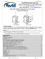
ATTACHMENTS
DISASSEMBLY AND ASSEMBLY
Removing the link
Fully retract the bucket cylinder and lower the front end of
the arm to the ground.
1. Pull out the cotter pin and remove the castle nut (1).
2. Suspend the bucket link (2) temporarily and remove
the pin (3).
• Place the bucket link on a skid.
• Be aware that one end of the guide link will fall down
when the pin (3) is pulled out.
3. Pull out the pin (4), and then remove the guide links L
(5) and R (6).
Installing the link
For installation of the link, follow the same procedure as for
removal in the reverse order.
Removing the arm
1. Disconnect the hydraulic hoses (1) from the bucket cyl-
inder (2).
Next, disconnect the hydraulic hoses from the auxiliary
ports (3).
2. Suspend the bucket cylinder (1) temporarily, pull out
the pin (4) and then remove the bucket cylinder
Bucket cylinder 32 kg
3. Place the arm cylinder on a skid and pull out the pin
(6).
4. Pull out the cotter pin and remove the castle nut (7).
5. Suspend the arm (8) temporarily, pull out the pin (9)
and then remove the arm.
Arm: 91 kg
Installing the arm
For installation of the arm, follow the same procedure as for
removal in the reverse order.
Important:
When securing the arm with the fixing pin (9) and the
castle nut (7), be sure not to overtighten the castle nut
(7).
Temporarily tighten the castle nut (7) by hand, adjust
the position so that the hole on the castle nut (7) aligns
with the fixing pin (9), and then secure the nut with a
cotter pin.
��������
�
�
�
�
�
�
��������
�
�
�
�
��������
�
�
�
�
�
Содержание TB 250
Страница 1: ......
Страница 3: ...1 1 SAFETY 1 Safety alert symbol 1 2 Safety precautions 1 3 Cautions when working 1 9...
Страница 36: ...2 24 2 TIGHTENING TORQUE SERVICE DATA...
Страница 37: ...2 25 2 SERVICE DATA HYDRAULIC CIRCUIT DIAGRAM HYDRAULIC CIRCUIT DIAGRAM Equipped with options 1 2...
Страница 38: ...2 26 2 HYDRAULIC CIRCUIT DIAGRAM SERVICE DATA Equipped with options 2 2...
Страница 39: ...2 27 2 HYDRAULIC CIRCUIT DIAGRAM SERVICE DATA Equipped with angle blade and blade oat 1 2...
Страница 40: ...2 28 2 HYDRAULIC CIRCUIT DIAGRAM SERVICE DATA Equipped with angle blade and blade oat 2 2...
Страница 41: ...2 29 2 HYDRAULIC CIRCUIT DIAGRAM SERVICE DATA Equipped with high ow option 1 2...
Страница 42: ...2 30 2 HYDRAULIC CIRCUIT DIAGRAM SERVICE DATA Equipped with high ow option 2 2...
Страница 43: ...2 31 2 HYDRAULIC CIRCUIT DIAGRAM SERVICE DATA Equipped with high ow angle blade blade oat option 1 2...
Страница 44: ...2 32 2 HYDRAULIC CIRCUIT DIAGRAM SERVICE DATA Equipped with high ow angle blade blade oat option 2 2...
Страница 46: ...2 34 2 ELECTRIC CIRCUIT DIAGRAM SERVICE DATA First auxiliary hydraulic piping with proportional control...
Страница 49: ......
Страница 59: ...2 46 2 WIRE HARNESS WIRING DIAGRAM SERVICE DATA...
Страница 60: ...2 47 2 WIRE HARNESS WIRING DIAGRAM SERVICE DATA...
Страница 61: ...2 48 2 WIRE HARNESS WIRING DIAGRAM SERVICE DATA...
Страница 62: ...2 49 2 WIRE HARNESS WIRING DIAGRAM SERVICE DATA...
Страница 63: ...2 50 2 WIRE HARNESS WIRING DIAGRAM SERVICE DATA...
Страница 64: ...2 51 2 WIRE HARNESS WIRING DIAGRAM SERVICE DATA...
Страница 65: ...2 52 2 WIRE HARNESS WIRING DIAGRAM SERVICE DATA...
Страница 66: ...2 53 2 WIRE HARNESS WIRING DIAGRAM SERVICE DATA...
Страница 67: ...2 54 2 WIRE HARNESS WIRING DIAGRAM SERVICE DATA...
Страница 68: ...2 55 2 WIRE HARNESS WIRING DIAGRAM SERVICE DATA...
Страница 69: ...2 56 2 WIRE HARNESS WIRING DIAGRAM SERVICE DATA...
Страница 70: ...2 57 2 WIRE HARNESS WIRING DIAGRAM SERVICE DATA...
Страница 71: ...2 58 2 WIRE HARNESS WIRING DIAGRAM SERVICE DATA...
Страница 72: ...2 59 2 WIRE HARNESS WIRING DIAGRAM SERVICE DATA...
Страница 73: ...2 60 2 WIRE HARNESS WIRING DIAGRAM SERVICE DATA NAME STANDARD NO...
Страница 74: ...2 61 2 WIRE HARNESS WIRING DIAGRAM SERVICE DATA...
Страница 75: ...2 62 2 WIRE HARNESS WIRING DIAGRAM SERVICE DATA...
Страница 76: ...2 63 2 WIRE HARNESS WIRING DIAGRAM SERVICE DATA...
Страница 77: ...2 64 2 WIRE HARNESS WIRING DIAGRAM SERVICE DATA...
Страница 78: ...2 65 2 WIRE HARNESS WIRING DIAGRAM SERVICE DATA...
Страница 79: ...2 66 2 WIRE HARNESS WIRING DIAGRAM SERVICE DATA...
Страница 80: ...2 67 2 WIRE HARNESS WIRING DIAGRAM SERVICE DATA...
Страница 81: ...2 68 2 WIRE HARNESS WIRING DIAGRAM SERVICE DATA...
Страница 92: ...3 11 3 CONTROL VALVE FUNCTION...
Страница 108: ...4 3 4 SERVICE STANDARDS DISASSEMBLY AND ASSEMBLY Clearance for pin and bushing...
Страница 130: ...4 25 4 UPPER FRAME DISASSEMBLY AND ASSEMBLY 15 Side frame R 16 Side frame L 17 Tool box 18 Cover 19 Bracket 20 Cover 2 2...
Страница 165: ...4 60 4 HYDRAULIC PUMP DISASSEMBLY AND ASSEMBLY f Remove the plug g Remove the spring and the ball...
Страница 267: ...4 162 4 SLEW MOTOR DISASSEMBLY AND ASSEMBLY Special tools Oil seal press tting jig A Collar installation jig B...
Страница 352: ...ENGINE 6 Machine model Mounted engine TB250 4TNV88...