3-23
3
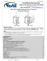
SLEW MOTOR
FUNCTION
Timer valve
This valve is used to prevent sudden operation of the park-
ing brake when the motor is stopped.
When the parking brake is activated, the pressure oil from
the port P4 is supplied at all times to the port PG, the spool
(1) is pushed to the right by the spring (2) force, and the
port PG is closed
When the slew pilot pressure or arm pilot pressure is di-
rected to the port SH, the force to move the spool (1) over-
comes the spring (2) force, and thus the spool (1) is move
to the left to open the port PG. The pressure oil from the
port PG flows through the hole at the center of the spool
(1) and the parking brake release port (PB) to release the
parking brake operation.
When the pilot pressure in the port SH disappears, the
spool (1) is moved to the right by the spring (2) force, the
port PG is closed, and the oil in the brake piston cham-
ber (3) is blocked. This enclosed oil gradually flows into the
drain port (dr) from the orifice located at the outer circum-
ference of the spool (1). As a result, the timer valve is used
as a timer, and thereby the parking brake does not start
working rapidly. It starts working after a certain time.
Reduction gears
The reduction gear is composed of a 2-stage planetary
gear mechanism, and it converts the high-speed operation
of the motor to the low speed torque to obtain the rota-
tional force of the pinion shaft (1).
In the figure on the right, the drive force transmitted from
the motor output shaft is transmitted to the second stage
sun gear (5) via the first stage drive gear (2), the planetary
gear (3) and the carrier 1 (4).
The drive force is transmitted in the same way to the pinion
shaft (1) via the second stage sun gear (5), the planetary
gear (6) and the carrier 2 (7), which becomes the drive force
for slewing.
��������
�
�
��
��
��
��������
�
�
�
�
��
��
��
��������
�
�
�
�
�
�
�
Содержание TB 250
Страница 1: ......
Страница 3: ...1 1 SAFETY 1 Safety alert symbol 1 2 Safety precautions 1 3 Cautions when working 1 9...
Страница 36: ...2 24 2 TIGHTENING TORQUE SERVICE DATA...
Страница 37: ...2 25 2 SERVICE DATA HYDRAULIC CIRCUIT DIAGRAM HYDRAULIC CIRCUIT DIAGRAM Equipped with options 1 2...
Страница 38: ...2 26 2 HYDRAULIC CIRCUIT DIAGRAM SERVICE DATA Equipped with options 2 2...
Страница 39: ...2 27 2 HYDRAULIC CIRCUIT DIAGRAM SERVICE DATA Equipped with angle blade and blade oat 1 2...
Страница 40: ...2 28 2 HYDRAULIC CIRCUIT DIAGRAM SERVICE DATA Equipped with angle blade and blade oat 2 2...
Страница 41: ...2 29 2 HYDRAULIC CIRCUIT DIAGRAM SERVICE DATA Equipped with high ow option 1 2...
Страница 42: ...2 30 2 HYDRAULIC CIRCUIT DIAGRAM SERVICE DATA Equipped with high ow option 2 2...
Страница 43: ...2 31 2 HYDRAULIC CIRCUIT DIAGRAM SERVICE DATA Equipped with high ow angle blade blade oat option 1 2...
Страница 44: ...2 32 2 HYDRAULIC CIRCUIT DIAGRAM SERVICE DATA Equipped with high ow angle blade blade oat option 2 2...
Страница 46: ...2 34 2 ELECTRIC CIRCUIT DIAGRAM SERVICE DATA First auxiliary hydraulic piping with proportional control...
Страница 49: ......
Страница 59: ...2 46 2 WIRE HARNESS WIRING DIAGRAM SERVICE DATA...
Страница 60: ...2 47 2 WIRE HARNESS WIRING DIAGRAM SERVICE DATA...
Страница 61: ...2 48 2 WIRE HARNESS WIRING DIAGRAM SERVICE DATA...
Страница 62: ...2 49 2 WIRE HARNESS WIRING DIAGRAM SERVICE DATA...
Страница 63: ...2 50 2 WIRE HARNESS WIRING DIAGRAM SERVICE DATA...
Страница 64: ...2 51 2 WIRE HARNESS WIRING DIAGRAM SERVICE DATA...
Страница 65: ...2 52 2 WIRE HARNESS WIRING DIAGRAM SERVICE DATA...
Страница 66: ...2 53 2 WIRE HARNESS WIRING DIAGRAM SERVICE DATA...
Страница 67: ...2 54 2 WIRE HARNESS WIRING DIAGRAM SERVICE DATA...
Страница 68: ...2 55 2 WIRE HARNESS WIRING DIAGRAM SERVICE DATA...
Страница 69: ...2 56 2 WIRE HARNESS WIRING DIAGRAM SERVICE DATA...
Страница 70: ...2 57 2 WIRE HARNESS WIRING DIAGRAM SERVICE DATA...
Страница 71: ...2 58 2 WIRE HARNESS WIRING DIAGRAM SERVICE DATA...
Страница 72: ...2 59 2 WIRE HARNESS WIRING DIAGRAM SERVICE DATA...
Страница 73: ...2 60 2 WIRE HARNESS WIRING DIAGRAM SERVICE DATA NAME STANDARD NO...
Страница 74: ...2 61 2 WIRE HARNESS WIRING DIAGRAM SERVICE DATA...
Страница 75: ...2 62 2 WIRE HARNESS WIRING DIAGRAM SERVICE DATA...
Страница 76: ...2 63 2 WIRE HARNESS WIRING DIAGRAM SERVICE DATA...
Страница 77: ...2 64 2 WIRE HARNESS WIRING DIAGRAM SERVICE DATA...
Страница 78: ...2 65 2 WIRE HARNESS WIRING DIAGRAM SERVICE DATA...
Страница 79: ...2 66 2 WIRE HARNESS WIRING DIAGRAM SERVICE DATA...
Страница 80: ...2 67 2 WIRE HARNESS WIRING DIAGRAM SERVICE DATA...
Страница 81: ...2 68 2 WIRE HARNESS WIRING DIAGRAM SERVICE DATA...
Страница 92: ...3 11 3 CONTROL VALVE FUNCTION...
Страница 108: ...4 3 4 SERVICE STANDARDS DISASSEMBLY AND ASSEMBLY Clearance for pin and bushing...
Страница 130: ...4 25 4 UPPER FRAME DISASSEMBLY AND ASSEMBLY 15 Side frame R 16 Side frame L 17 Tool box 18 Cover 19 Bracket 20 Cover 2 2...
Страница 165: ...4 60 4 HYDRAULIC PUMP DISASSEMBLY AND ASSEMBLY f Remove the plug g Remove the spring and the ball...
Страница 267: ...4 162 4 SLEW MOTOR DISASSEMBLY AND ASSEMBLY Special tools Oil seal press tting jig A Collar installation jig B...
Страница 352: ...ENGINE 6 Machine model Mounted engine TB250 4TNV88...