XT-1 Installation Manual
13-111 02, 2014-RO-012, 2014-04-30
Page 9 of 32
Wires
3.2.1 Terminal Connections
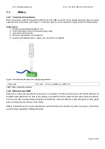
Wire connections (with the exception of Ethernet and USB, see §3.2.2) are added as single wires to spring
cage terminal connectors, see Figure 7. These are easy-to-use terminals for single solid or stranded wires.
Instructions:
1. Strip wire lead approximately 9 mm.
2. Push screwdriver down to release spring cage.
3. Insert wire into terminal.
4. Remove screwdriver to clamp wire.
5. Gently pull installed wire to make sure connection is reliable.
Figure 7 Connection with easy-to-use spring cage terminal
Wire size
0.5 mm
2
- 1.5 mm
2
(AWG 20 - AWG 16)
Table 1 Wire connection overview
3.2.2 Ethernet and USB
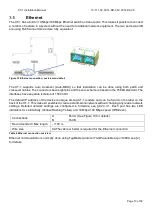
Ethernet is connected using RJ45 connectors. To be able to fit this connector given the limited diameter of
the M20 cable gland and the hole in the chassis, such RJ45 must be crimped to the wires inside the reader.
This is done with corresponding standard tool and RJ45. Pass the Ethernet cable through the cable gland
before crimping the connector on the cable.
USB is intended for service and maintenance and is therefore connected only when lid is open. Connection
is done using a standard USB type B cable.


