6 / GRAND SLAM 1000
1. Remove the tie wraps securing the upper and lower mounting plates together.
2. Place a thin bead of marine-grade sealant under the mounting plate.
3. Secure the head using the 5/16”-18 bolts.
4. Through the lower access plate, verify all tubing is not kinked. Manually rotate head 90º to ensure it
rotates freely.
5. Refer to the “Operation” section of this manual and cycle the rotation of each head through several
full rotations to bleed the rotation system.
6. Install Outriggers per manufactures instructions.
Install the Heads
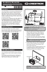
1. A
- Main Power Switch: activates all features of the mount.
2. B
- Safety Lock button: Switch must be held in the depressed position to allow operation of the
Rotation Switch
(D)
. This prevents unintentional rotation of the outrigger arm.
3. C
- Port/ Starboard Select Switch: This switch selects Lift
(E)
and Rotation
(D)
access to the selected
outrigger.
4. D
- Momentary Switch: When used in conjunction with the Unlock Switch to provide rotation to the
head. The arm can be stopped at any position between 0° and 90°.
5. E
- Lift/Lower Momentary Switch: This switch provides vertical lift of the outrigger with stops at 30°,
45°, 60° and 75°. Each momentary push of the button raises or lowers to the next position.
6. F
- Position indicator LEDs: These will be illuminated with the position of the Port and Starboard
outrigger at 0°. 30°, 45°, 60° and 75°
A
- Main Power Switch
B
- Safety Unlock Button
C
- Port/Starboard Select
D
- Rotation Switch
E
- Lift/Lower Switch
F
- Position LED
OPERATION & MAINTENANCE
Control Panel & Operation
Содержание GRAND SLAM 1000
Страница 9: ...GRAND SLAM 1000 9 Keypad Interface...
Страница 12: ...12 GRAND SLAM 1000 LEFT BLANK INTENTIONALLY...
Страница 14: ...INSTRUCT GS 1000...