12/03/2012
22
GI301
Mechanical Installation Refrigeration
Overview
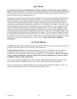
The TTHERM GEO Series split unit includes pre-charged R-410A, with the filter drier factory installed in the
unit.
The charge may need to be fine tuned
based upon line set length and system performance. Line set
lengths of over 25ft (7.6 meters) are not recommended due to performance loss and potential oil return issues.
Forced Air Coil
– The refrigerant coil supplied with this product model number must be used for this
installation. The nameplate and specification table ratings only apply when using the furnished air coil.
Provisions and plenum arrangements must be made to accommodate the coil. This is necessary
again for proper Geo HP performance and meeting specification requirements, Energy Star, ARI,
etc.
Airflow (minimum CFM) is also a key requirement for proper performance and rating, see previous
section.
Line Set Information
– Factory charge is set to include enough refrigerant for 10ft (3 meters) of line set and the
forced air coil provided. If a line set of more than 10ft is used, additional R-410A refrigerant is required to be
added to the system. Added amount of refrigerant needed is based upon 0.5oz per ft for 3/8” and 1.0oz per ft for
1/2" liquid lines.
Tube diameters and lengths for the line set are determined using the table on the following page. The suction
lines must be insulated. When handling the line set, ensure that no kinks occur when bending the tubes into
position. If one of the tubes happens to kink and it cannot be fully removed, the tube must be replaced. A kink
in a tube will adversely affect system performance.
When installing the line set, it is imperative that the lines do not come in direct contact with any other
surfaces.
Adhering to this practice will further reduce any chance of compressor vibration transmitting into
other areas of the building. When hangers are necessary; use hangers that incorporate isolation sleeves.
Refrigerant Installation Practices
– The line sets, recharging, and charge verification must be done by a
professional/licensed refrigeration technician. Industry standard and proper cleaning, nitrogen flow, brazing
techniques, and leak verification must be followed with this installation. Brazed connections points on both the
compressor side and air coil side of the line set are required.
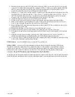
During the brazing process, it is critical that 2-3
psi of nitrogen be circulated through the system in order to prevent internal oxidation
. Low silver phos-
copper braze alloy shall also be used on all brazed connection points.
Before brazing, wrap the service valves with a heat sink to prevent damage caused by excessive heat.
This unit
is shipped with a factory charge, DO NOT open the service valves until the line set has been leak tested,
purged, and evacuated.
Depending upon the length of the line set, copper adapters may be needed to
accommodate larger diameter tubing.
Proper evacuation (500 microns) must take place prior to opening the main unit ball valves.
Once the service valves have been opened, the
final charge
may need to be fine tuned based upon the sub-
cooling and superheat chart.
Содержание TST-***
Страница 8: ...12 03 2012 6 GI301 Product Dimensions Forced Air Coil Reference Information...
Страница 22: ...12 03 2012 20 GI301...
Страница 48: ......
Страница 51: ......


