28
29
tube·amp·company
tube·amp·company
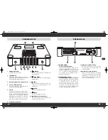
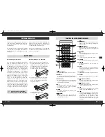
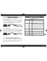
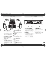
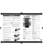
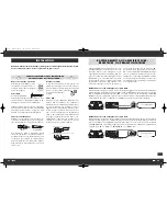
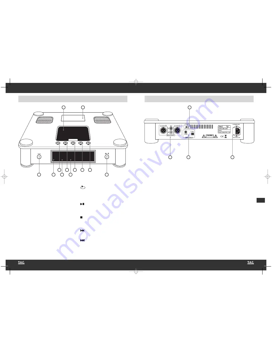
REAR VIEW
1. POWER
This is the main power switch for turning on and
off the device.
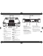
2. LED “WARM UP”
This LED is blinking for about 20 seconds while
after switching on the tubes of the internal ampli-
fier are being warmed up.
3. Infrared receiver for the remote control
4. Display
The display shows track number, elapsed playing
time and other information.
5. CD chamber
In order to insert a CD the cover of this chamber
can be opened by sliding it towards the back of
the CD player. After positioning the CD on the
centre spindle inside the CD chamber the magnet
clamp must be attached on top of the CD central
bore. Close the chamber cover by sliding it all the
way towards the CD player front panel.
6. Illuminatable name plate
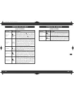
7.
(REPEAT)
Activate and deactivate the repeat function that
allows you to replay a single track or the comple-
te CD content with this key.
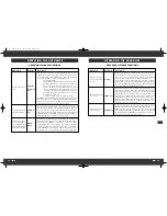
8.
(PLAY/PAUSE)
The purpose of this key is starting or interrupting
the playback of the CD.
9.
(STOP)
Stops the current playback of a CD or switches
from pause to the player’s initial state.
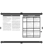
10.
(BACK)
Key for going back one track.
11.
(NEXT)
Key for stepping forward one track.
12. TUBE/FET: amplification mode switch
Toggle between tube amplification and transistor
amplification.
FRONT VIEW
1
12
2
3
4
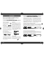
13. ANALOG OUTPUT:
analogue audio signal outputs
Either the RCA connector pair or the XLR sockets
(“BALANCED”) must be connected to the corre-
sponding input of the amplifier, preamplifier etc.
It is not necessary to also connect one of the digi-
tal signal outputs (14).
14. DIGITAL OUTPUT: digital audio
signal outputs (coaxial and optical)
If the amplifier, receiver or preamplifier is equip-
ped with a digital coaxial or optical digital input
connector, the corresponding CD player signal
output may be connected to this. It is not necessa-
ry to connect an analogue (13) and a digital
signal output (14) at the same time.
15. LAMP: name plate illumination
Activate the name plate (6) illumination by setting
this switch to the position “ON” or deactivate it
by setting the switch to the alternative position
“OFF”.
16. AC power connector and fuse holder
To establish the power supply, connect the plugs
of the power cable to the device and to a wall
power outlet. The small plastic housing on the left
side of the plug opening holds the fuse. Refer to
the security precautions.
13
14
16
7
8
9
10
11
5
6
15
C-60 24.04.2009 16:53 Uhr Seite 28


