10
installation manual
NOTE
Please remember the surroundings (environmental
temperature, direct sunlight, rain etc.)
We consider the minimal size of the metal core as the wire
size. So it is recommended you adopt a thicker one as the
power conducting wire so as to avoid power decrease;
Connect the grounded wire to both indoor and outdoor
units;
This chart is just an on-site wire-connecting example.
For details, please refer to relative National criteria.
Indoor
Unit
Outdoor
Unit
A
B
Distance between outdoor unit and the farthest indoor
unit
ӊ
1200m (Note: The length of signal wire depends
on actual wiring condition, not longer than 1200m)
Entrance
of the Indoor Unit
Entrance
of the outdoor Unit
A, B
ӊ
20m
Wiring chart
CENTRAL CONTROL
MONITOR(CCM)
OUTDO OR UNIT
COMPUTER
I NDOOR UNIT
I NDOOR UNIT
I NDOOR UNIT
Power (220-240V ~ 50Hz)
(208-230V ~ 60Hz)
Fig.9-1
The reserved function
is indicated in broken
line table, users can
select it when
necessary
3-core shielded wire
A disconnection device having an air gap contact separation in
all active conductors should be incorporated in the fixed wiring
according to the National Wiring Regulation.
Ground the air conditioner properly to obtain a good anti-
interference effect .
CAUTION
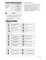
Model(W)
1500~5600
15/15
3×2.0
Circuit breaker/fuse (A)
Indoor unit power wiring (mm
2
)
Indoor/outdoor
connecting wiring(mm
2
)
(weak electric signal)
Power
Phase
1-Phase
220-240~50Hz
Frequency and volt
Table.9-1
3-core shielded wire
3×0.5
NOTE
The air-conditioners can connect with Central Control
Monitor (CCM). Before operation, please wiring correctly
and set system address and network address of indoor
units.
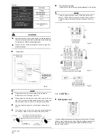
Terminal board diagram
Please refer to the indoor unit wiring diagram for the wiring.
<*
/
1
;7
TO INDOOR POWER
220-240V~50Hz
208-230V~60Hz
Fig.9-2
Fig.9-3
:+,7(
%/8(
%/$&.
P Q
X Y E
<(//2:
*5$<
TO OUTDOOR
COMM. BUS
To Central Control Monitor
(CCM)COMM. BUS
;7
Please use 3-core shielded wire,and
connect the shielded layer to the earth
10. CONTROL
208-230~60Hz
<*
Display
board
Wire
controller
To wire controller
The reserved wire control
function is indicated in broken
table, user can purchase the
wire controller when necessary.
Fig.9-4
%/$&.
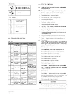
Base on different purposes to setting the switch cords on PC panel
of indoor electrical control box. Once finish the setting, please cut off
the main power, and then input power again, otherwise, setting
function could not work.
Horsepower set
Horsepower code
0 1
2
3
4
5
6
7
8 9
A
B
C
D
E
F
ENC1
PO WER_S

