SS-400-012 9 I56-3749-006
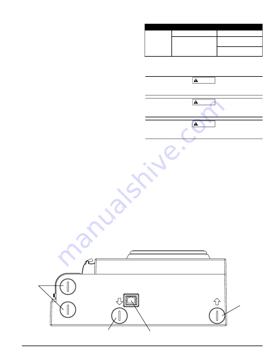
FIGURE 14. BOTTOM VIEW OF UNIT
Wiring
Access
Plugs
Sampled
Air Inlet
Sampled
Air Outlet
Network
Connection
ASP03-00
WEB SERVER
The FAAST system contains an integrated Web server which is used to ob-
serve detector configuration and may be used to remotely monitor the unit.
The Web server features include:
• Intuitive interface for remote monitoring of faults, relays, particulate
level, air flow, and power supply
• Facility location and contact information
• Configuration settings display
• Multi-Lingual support
• Event log viewer
E-MAIL NOTIFICATION
The FAAST system has the ability to send e-mail notifications to an individual
or organization. Up to 6 different email addresses may be stored for notifica-
tion. Each email address can be configured to be notified of a specific alarm
level, fault level or isolate condition through the PipeIQ software. E-mails from
the device indicate a device’s ID, location and alarm or fault type. A com-
prehensive networking guide may be downloaded at systemsensor.com/faast.
CANNED SMOKE TESTING
All FAAST systems must be tested after installation and periodically thereafter.
Testing methods must statisfy the authority having jurisdiction. Systems of-
fer maximum performance when tested and maintained in compliance with
CAN/ULC S536. UL Tested and approved aerosol smoke products are listed
in Table 6.
MAINTENANCE
The only periodic maintenance required is to replace the filter assembly when
the filter light is illuminated. Perform the following procedure to replace the
filter assembly.
1. Remove power from the system.
2. Open the door on the right side of the device that covers the LED system
indicators.
3. Remove the plastic name card over the LEDs.
4. Remove the two screws holding the filter assembly into the device.
5. Remove the filter assembly and replace it with a new assembly.
6.
Install the two screws to hold the filter assembly into the device.
Torque the two Philips head screws to 6 in-lb (0.7 N-m) or 1/4 turn past
“lightly snug”. Do not over tighten.
7. Replace the plastic name card over the LEDs.
8. Close the door and return power to the system.
Other system checks may need to be performed in accordance with local or
national codes and regulations.
CLASS I, DIVISION II
This equipment is suitable for use in Class I, Division 2, Class A, B, C and D
OR non-hazardous environments only.
WARNING
EXPLOSION HAZARD - do not disconnect equipment unless power has been
removed or the area is known to be non-hazardous
WARNING
EXPLOSION HAZARD - Substitution of any components may impair suitabil-
ity for Class I, Division 2
WARNING
Exposure to some chemicals may degrade the sealing properties of materials
used in the relays.
ULC LISTED
COMPANY
AEROSOL
Home Safeguard
25S
No Climb
SOLOA4
SMOKE SABRE-01
TABLE 6. CANNED SMOKE TESTING


