Protouch-wide: user documentation
DOC/PROTOUCH-WIDE; V1.5
DOC_PROTOUCH_WIDE_V1.5.docx
Seite 31 von 41
© 2019 Syslogic Datentechnik AG | All rights reserved
3.2.5
Cabling of communication links
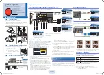
If the communication ports are non-isolated ports, cable shields have to be connected to chassis potential on both sides of the interconnection
cable. If the cable is very long, a thick copper wire (10 mm
2
) for potential adjustment is highly recommended. Fig. 12 shows a non-isolated
system with common chassis ground.
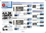
Some of the communication ports are galvanically isolated ports. In such cases the shield of the interconnection cable must be wired to chassis
potential only on one side of the cable. Fig. 11 shows an isolated system with independent grounds.
Important
Note
Grounding of the cable’s shields using
pig-tail wires
is not recommended because of their high
impedance at high frequencies. It is better to clamp the shields onto a grounded copper rail.
Fig. 11
Isolated communication link
Fig. 12
Non-isolated communication link with common chassis potential
Unisolated Node
24 VDC
24 VDC
0 VDC
0 VDC
100E
100E
Zentraler Erdpunkt am Chassis
Central Grounding Point
Zentraler Erdpunkt am Chassis
Central Grounding Point
I/O
Communication Link
Abschirmung/Shield
Unisolated Node
IPC System Nr. 1
IPC System Nr. 2
Potential-Ausgleichsleitung min. 10 mm
2
Kupfer
Copper-wire for Potential Adjustment, min. 10 mm
2
I/O
Isolated Node
24 VDC
24 VDC
0 VDC
0 VDC
100E
100E
Opto
Zentraler Erdpunkt am Chassis
Central Grounding Point
Zentraler Erdpunkt am Chassis
Central Grounding Point
I/O
Communication Link
Abschirmung/Shield
Achtung: keine Verbindung
des Kabelmantels mit dem Chassis
Do not connect cable-shield with
chassis, floating operation
Unisolated Node
IPC System Nr. 1
IPC System Nr. 2
I/O


