Getting
Started
©
SYS TEC electronic GmbH 2007 L-1032e_9
13
3.4
Switches
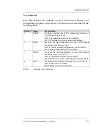
Four DIP-switches are available on the CAN-Ethernet Gateway for
configuration purposes of the device. Their function is described in the
following table:
Switch # Name
Description
1
TERM
Defines whether the CAN terminating resistor of
120 Ohm is active or not
ON
Æ
terminating resistor active/enabled
OFF
Æ
terminating resistor not active/disabled
2
DEFT
Defines the start initialization of the CAN-Ethernet
Gateway
(refer to section 3.5)
ON
Æ
factory default configuration will be loaded
OFF
Æ
user configuration will be loaded
3
BOOT
Activate the “Bootstrap-Mode” of the CAN-Ethernet
Gateway
(refer to section 8)
ON
Æ
“Bootstrap-Mode” will be entered
OFF
Æ
Firmware of the CAN-Ethernet Gateway starts
4
RES
Reset the CAN-Ethernet Gateway
(refer to section 8)
ON
Æ
Reset active/enabled
OFF
Æ
Reset not active/disabled
Table 5:
Meaning of the Switches
Содержание GW-003
Страница 1: ...system house for distributed automation CAN Ethernet Gateway GW 003 Systems Manual Edition April 2007 ...
Страница 5: ...Contents SYS TEC electronic GmbH 2007 L 1032e_9 Index 97 ...
Страница 8: ...CAN Ethernet Gateway SYS TEC electronic GmbH 2007 L 1032e_9 ...
Страница 14: ...CAN Ethernet Gateway 6 SYS TEC electronic GmbH 2007 L 1032e_9 ...
Страница 56: ...CAN Ethernet Gateway 48 SYS TEC electronic GmbH 2007 L 1032e_9 ...
Страница 66: ...CAN Ethernet Gateway 58 SYS TEC electronic GmbH 2007 L 1032e_9 ...
Страница 100: ...CAN Ethernet Gateway 92 SYS TEC electronic GmbH 2007 L 1032e_9 ...
Страница 108: ...Published by SYS TEC electronic GmbH 2007 Ordering No L 1032e_9 Printed in Germany ...


