

2-3-4
Z13N4HMA
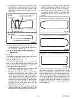
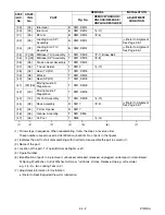
5. To shift the CTL waveform, press CH UP or CH
DOWN button on the remote control unit. Then
make sure that the maximum output position of PB
FM envelope signal become within
±
2ms from pre-
set position.
6. Set the Tracking Control Circuit to the preset posi-
tion by pressing CH UP button on the remote con-
trol unit. and then “PLAY” button.
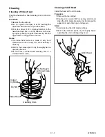
1-C. Checking/Adjustment of Envelope
Waveform
Purpose:
To achieve a satisfactory picture, adjust the PB FM
envelope becomes as flat as possible.
Symptom of Misalignment:
If the envelope output is poor, noise will appear in the
picture. The tracking will then lose precision and the
playback picture will be distorted by any slight varia-
tion of the Tracking Control Circuit.
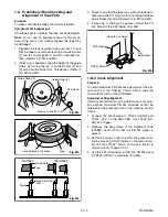
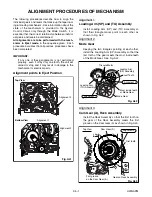
1. Connect the oscilloscope to TP402 (V-ENV) on the
Main CBA. Use TP202 (RF-SW) as a trigger.
2. Playback the Gray Scale on the Alignment Tape
(FL8NW). Set the Tracking Control Circuit to the
preset position by pressing CH UP button and then
“PLAY” button on the unit. Adjust the height of
Guide Rollers [2] and [3] (Fig. M3, Page 2-3-3)
watching the oscilloscope display so that the enve-
lope becomes as flat as possible. To do this adjust-
ment, turn the top of the Guide Roller with the
Guide Roller Adj. Screwdriver.
3. If the envelope is as shown in Fig. M7, adjust the
height of Guide Roller [2] (Refer to Fig. M3) so that
the waveform looks like the one shown in Fig. M9.
4. If the envelope is as shown in Fig. M8, adjust the
height of Guide Roller [3] (Refer to Fig. M3) so that
the waveform looks like the one shown in Fig. M9.
5. When Guide Rollers [2] and [3] (Refer to Fig. M3)
are aligned properly, there is no envelope drop
either at the beginning or end of track as shown in
Fig. M9.
Note: Upon completion of the adjustment of Guide
Rollers [2] and [3] (Refer to Fig. M3), check the X
Value by pushing the CH UP or DOWN buttons alter-
nately, to check the symmetry of the envelope. Check
the number of pushes to ensure preset position. The
number of pushes CH UP button to achieve 1/2 level of
envelope should match the number of pushes CH
DOWN button from center. If required, redo the “X
Value Alignment.”
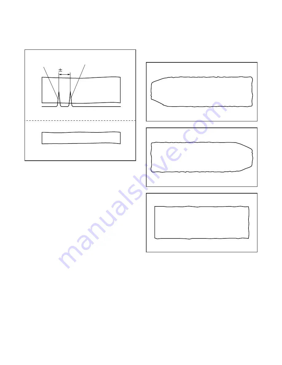
Fig. M7
No Good
Good
FM envelope output signal is low.
FM envelope output signal
is adjusted at maximum.
FM envelope signal
Preset position
Maximum output position of
PB FM envelope signal
CTL signal
2ms
Fig. M8
Dropping envelope level at the beginning of track.
Fig. M9
Dropping envelope level at the end of track.
Fig. M10
Envelope is adjusted properly. (No envelope drop)
Содержание SRC2213W
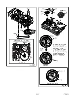
Страница 17: ...1 5 2 T5505DC S 1 1 REAR CABINET S 1 S 2 Fig 1 Fig 2 1 REAR CABINET S 1 S 2 S 1 S 1 S 1 ...
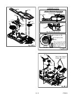
Страница 18: ...1 5 3 T5505DC Fig 3 2 TRAY CHASSIS 3 DECK UNIT S 3 S 3 S 3 4 MAIN CBA S 6 S 5 S 4 S 6 S 6 S 6 S 7 ...
Страница 19: ...1 5 4 T5505DC Fig 4 S 8 S 8 S 8 S 8 ANODE CAP 5 CRT CRT CBA ...
Страница 22: ...1 5 7 T7505DC ANT 1 REAR CABINET Fig 1 S 1 S 1 S 1 S 2 Fig 2 1 REAR CABINET S 1 S 1 S 2 S 1 S 1 ...
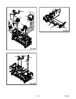
Страница 23: ...1 5 8 T7505DC Fig 3 S 6 S 5 S 4 S 6 S 6 S 6 S 7 S 3 S 3 2 TRAY CHASSIS 3 DECK UNIT 4 MAIN CBA S 3 ...
Страница 24: ...1 5 9 T7505DC Fig 4 S 8 S 8 S 8 S 8 5 CRT CRT CBA ANODE CAP ...
Страница 65: ...1 14 5 T5505PEX Packing SRC2213W X3 X4 X2 TAPE X1 X5 S2 S6 S3 S1 S4 FRONT ...
Страница 66: ...1 14 6 T7505PEX SRC2419 X1 S1 S4 S3 S3 S2 TAPE TAPE X4 X3 X2 S6 S14 FRONT ...
Страница 103: ...SRC2213W SRC2419 T5505UF T7505UF Printed in Japan 2004 03 20 HO ...