
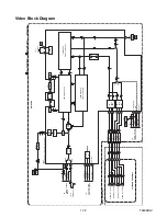
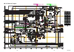
1-6-7
T5505EA
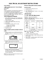
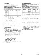
The following 2 adjustments normally are not
attempted in the field. They should be done
only when replacing the CRT then adjust as a
preparation.
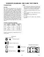
12.Purity Adjustment
Purpose:
To obtain pure color.
Symptom of Misadjustment:
If Color Purity Adjust-
ment is incorrect, large areas of color may not be prop-
erly displayed.
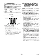
* This becomes RED COLOR if push 7KEY with a
service mode.
1. Set the unit facing east.
2. Operate the unit for over 30 minutes before adjust-
ing.
3. Fully degauss the unit using an external degauss-
ing coil.
4. Set the unit to the AUX mode which is located
before CH2 then input a red raster from video in.
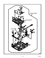
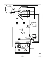
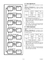
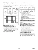
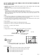
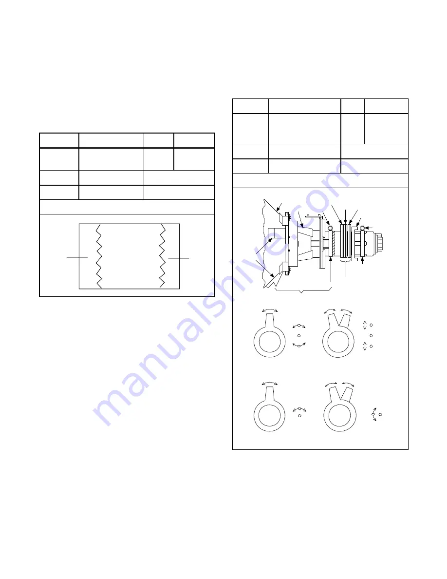
5. Loosen the screw on the Deflection Yoke Clamper
and pull the Deflection Yoke back away from the
screen. (See Fig. 6.)
6. Loosen the Ring Lock and adjust the Purity Mag-
nets so that a red field is obtained at the center of
the screen. Tighten Ring Lock. (See Fig. 5,6.)
7. Slowly push the Deflection Yoke toward the bell of
the CRT and set it where a uniform red field is
obtained.
8. Tighten the clamp screw on the Deflection Yoke.
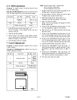
13. Convergence Adjustment
Purpose:
To obtain proper convergence of red, green
and blue beams.
Symptom of Misadjustment:
If Convergence Adjust-
ment is incorrect, the edge of white letters may have
color edges.
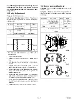
Test point
Adj. Point
Mode
Input
---
Deflection Yoke
Purity Magnet
---
*Red Color
Tape
M. EQ.
Spec.
---
Pattern Generator
See below.
Figure
BLUE
GREEN
RED
Fig. 5
Test point
Adj. Point
Mode
Input
---
C.P. Magnet (RB),
C.P. Magnet (RB-G),
Deflection Yoke
---
Dot Pattern
or
Crosshatch
Tape
M. EQ.
Spec.
---
Pattern Generator
See below.
Figure
DY WEDGE
DEFLECTION YOKE
C.P. MAGNET
RING LOCK
SCREW
SCREW
RB-G
RB
PURITY
CRT
COIL
COIL CLAMPER
C.P. MAGNET
CLAMPER
Fig. 6
Fig. 7
Fig. 8
B
G
R
R
G
B
C.P. MAGNET (RB)
RB
G
RB
G
C.P. MAGNET (RB-G)
Содержание SRC2213W
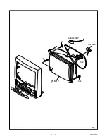
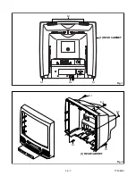
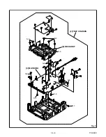
Страница 17: ...1 5 2 T5505DC S 1 1 REAR CABINET S 1 S 2 Fig 1 Fig 2 1 REAR CABINET S 1 S 2 S 1 S 1 S 1 ...
Страница 18: ...1 5 3 T5505DC Fig 3 2 TRAY CHASSIS 3 DECK UNIT S 3 S 3 S 3 4 MAIN CBA S 6 S 5 S 4 S 6 S 6 S 6 S 7 ...
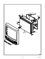
Страница 19: ...1 5 4 T5505DC Fig 4 S 8 S 8 S 8 S 8 ANODE CAP 5 CRT CRT CBA ...
Страница 22: ...1 5 7 T7505DC ANT 1 REAR CABINET Fig 1 S 1 S 1 S 1 S 2 Fig 2 1 REAR CABINET S 1 S 1 S 2 S 1 S 1 ...
Страница 23: ...1 5 8 T7505DC Fig 3 S 6 S 5 S 4 S 6 S 6 S 6 S 7 S 3 S 3 2 TRAY CHASSIS 3 DECK UNIT 4 MAIN CBA S 3 ...
Страница 24: ...1 5 9 T7505DC Fig 4 S 8 S 8 S 8 S 8 5 CRT CRT CBA ANODE CAP ...
Страница 65: ...1 14 5 T5505PEX Packing SRC2213W X3 X4 X2 TAPE X1 X5 S2 S6 S3 S1 S4 FRONT ...
Страница 66: ...1 14 6 T7505PEX SRC2419 X1 S1 S4 S3 S3 S2 TAPE TAPE X4 X3 X2 S6 S14 FRONT ...
Страница 103: ...SRC2213W SRC2419 T5505UF T7505UF Printed in Japan 2004 03 20 HO ...


