
1-6-2
T5505EA
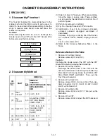
[ SRC2419 ]
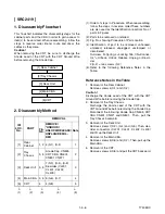
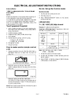
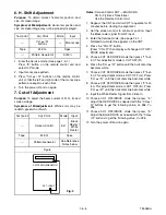
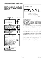
1-2. DC 114V (+B) Adjustment
Purpose:
To obtain correct operation.
Symptom of Misadjustment:
The picture is dark and
unit does not operate correctly.
Note:
D613 Cathode (+B), C613(-) (GND),
VR601 --- Main CBA
1. Connect the unit to AC Power Outlet.
2. Connect DC Volt Meter to D613 Cathode (+B) and
C613(-) (GND).
3. Adjust VR601 so that the voltage of D613 Cathode
(+B) b114
±
0.5V DC.
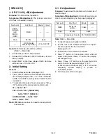
2. Initial Setting
General
1. Enter the Service mode. (See page 1-4-1)
2. Press "VOL
p
" button on the service remote control
unit. Display changes "C/D," "7F," "FM," "ACCESS
CODE," and "RC5" cyclically when "VOL
p
" button
is pressed.
3. To set each data value shown below, press "CH
o
/
p
" buttons on the service remote control unit.
7F --- Set to "FF."
FM --- Set to "ON." [ SRC2213W ]
Set to "OFF." [ SRC2419 ]
ACCESS CODE --- Set to "ON."
RC5 --- Set to "OFF."
Note:
C/D
data value does not need to be adjusted at
this moment.
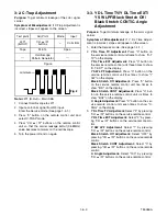
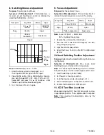
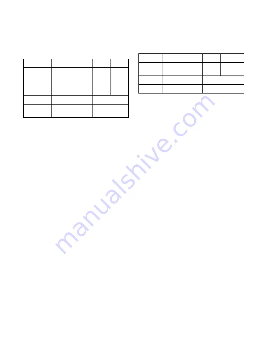
3-1. H Adjustment
Purpose:
To get correct horizontal position and size of
screen image.
Symptom of Misadjustment:
Horizontal position and
size of screen image may not be properly displayed.
Note:
R583 --- Main CBA
1. Connect Frequency Counter to R583.
2. Set the unit to the VIDEO mode and no input is
necessary. Enter the Service mode.
(See page 1-4-1.)
3. Operate the unit for at least 20 minutes.
4. Press "2" button on the remote control unit and
select H-Adj mode. (Press "2" button, then display
will change H-Adj.)
5. Press "CH
o
/
p
" buttons on the remote control
unit so that the display will change "0" to "7."
At this moment, choose display "0" to "7" when the
Frequency counter display is closest to
15.734kHz
±
300Hz.
6. Turn the power off and on again.
Test point
Adj. Point
Mode
Input
D613
Cathode
(+B)
C613(-)
(GND)
VR601
---
-----
Tape
M. EQ.
Spec.
---
DC Voltmeter
Plastic Tip Driver
+114
±
0.5V DC
Test point
Adj. Point
Mode
Input
R583
CH
o
/
p
buttons
Video
---
Tape
M. EQ.
Spec.
---
Frequency Counter
15.734kHz
±
300Hz
Содержание SRC2213W
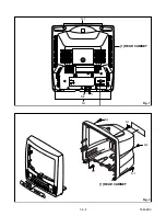
Страница 17: ...1 5 2 T5505DC S 1 1 REAR CABINET S 1 S 2 Fig 1 Fig 2 1 REAR CABINET S 1 S 2 S 1 S 1 S 1 ...
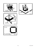
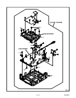
Страница 18: ...1 5 3 T5505DC Fig 3 2 TRAY CHASSIS 3 DECK UNIT S 3 S 3 S 3 4 MAIN CBA S 6 S 5 S 4 S 6 S 6 S 6 S 7 ...
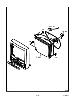
Страница 19: ...1 5 4 T5505DC Fig 4 S 8 S 8 S 8 S 8 ANODE CAP 5 CRT CRT CBA ...
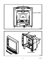
Страница 22: ...1 5 7 T7505DC ANT 1 REAR CABINET Fig 1 S 1 S 1 S 1 S 2 Fig 2 1 REAR CABINET S 1 S 1 S 2 S 1 S 1 ...
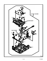
Страница 23: ...1 5 8 T7505DC Fig 3 S 6 S 5 S 4 S 6 S 6 S 6 S 7 S 3 S 3 2 TRAY CHASSIS 3 DECK UNIT 4 MAIN CBA S 3 ...
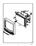
Страница 24: ...1 5 9 T7505DC Fig 4 S 8 S 8 S 8 S 8 5 CRT CRT CBA ANODE CAP ...
Страница 65: ...1 14 5 T5505PEX Packing SRC2213W X3 X4 X2 TAPE X1 X5 S2 S6 S3 S1 S4 FRONT ...
Страница 66: ...1 14 6 T7505PEX SRC2419 X1 S1 S4 S3 S3 S2 TAPE TAPE X4 X3 X2 S6 S14 FRONT ...
Страница 103: ...SRC2213W SRC2419 T5505UF T7505UF Printed in Japan 2004 03 20 HO ...


